A - 4
(2) Wiring
CAUTION
Before removing the CNP1 connector of MR-JE-40C to MR-JE-100C, disconnect the lead wires of the
regenerative resistor from the CNP1 connector.
Wire the equipment correctly and securely. Otherwise, the servo motor may operate unexpectedly.
Make sure to connect the cables and connectors by using the fixing screws and the locking mechanism.
Otherwise, the cables and connectors may be disconnected during operation.
Do not install a power capacitor, surge killer, or radio noise filter (optional FR-BIF) on the servo amplifier
output side.
To avoid a malfunction, connect the wires to the correct phase terminals (U/V/W) of the servo amplifier
and servo motor.
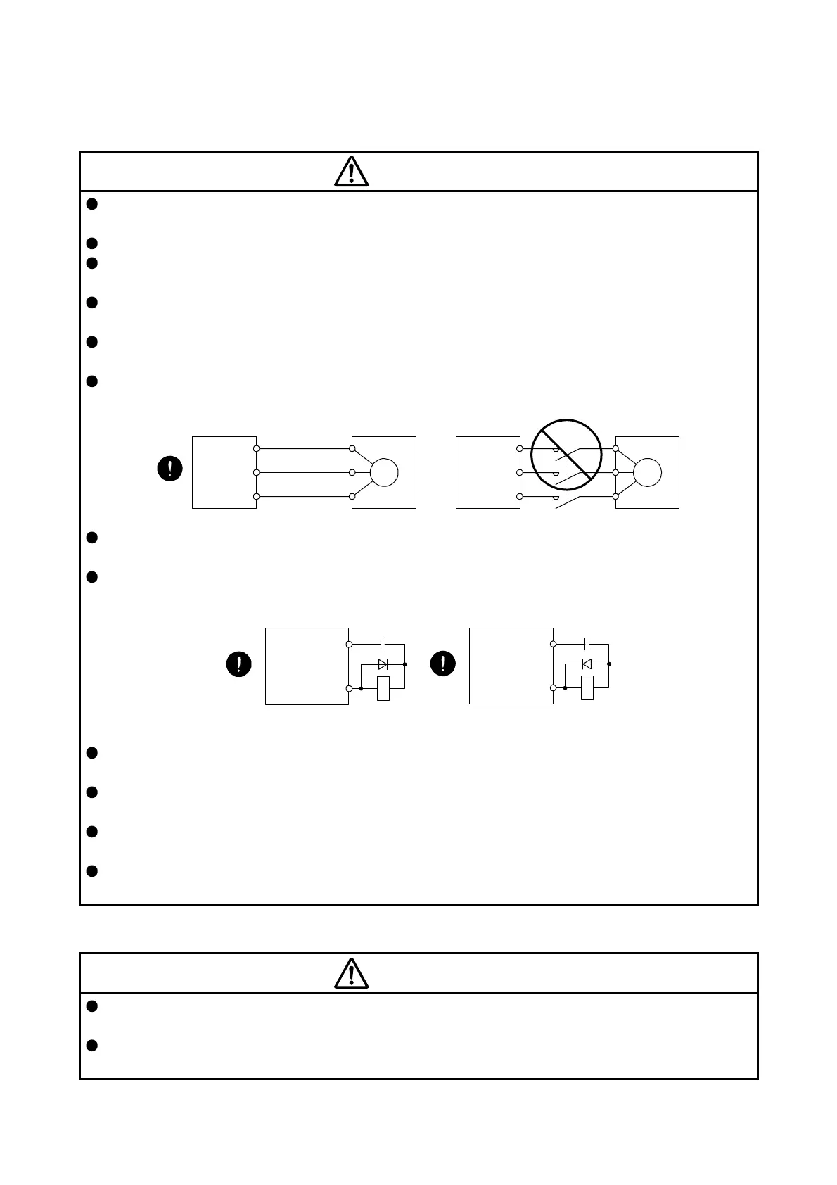
Connect the servo amplifier power output (U/V/W) to the servo motor power input (U/V/W) directly. Do
not let a magnetic contactor, etc. intervene. Otherwise, it may cause a malfunction.
U
Servo motor
M
V
W
U
V
W
U
M
V
W
U
V
W
Servo amplifier
Servo motorServo amplifier
The connection diagrams in this instruction manual are shown for sink interfaces, unless stated
otherwise.
The surge absorbing diode installed to the DC relay for control output should be fitted in the specified
direction. Otherwise, the emergency stop and other protective circuits may not operate.
DOCOM
Control output
signal
Servo amplifier
RA
For sink output interface
24 V DC
DOCOM
Control output
signal
24 V DC
Servo amplifie
RA
For source output interface
When the cable is not tightened enough to the terminal block, the cable or terminal block may generate
heat because of the poor contact. Be sure to tighten the cable with specified torque.
Connecting a servo motor of the wrong axis to U, V, W, or CN2 of the servo amplifier may cause a
malfunction.
Configure a circuit to turn off EM2 or EM1 when the power supply is turned off to prevent an unexpected
restart of the servo amplifier.
To prevent malfunction, avoid bundling power lines (input/output) and signal cables together or running
them in parallel to each other. Separate the power lines from the signal cables.
(3) Test run and adjustment
CAUTION
When executing a test run, follow the notice and procedures in this instruction manual. Otherwise, it may
cause a malfunction, damage to the machine, or injury.
Before operation, check the parameter settings. Improper settings may cause some machines to operate
unexpectedly.
 Loading...

