10
LOADING AND INSTALLATION
10.1 General Safety Requirements
10 - 5
9
EMC AND LOW
VOLTAGE
DIRECTIVES
10
LOADING AND
INSTALLATION
11
MAINTENANCE AND
INSPECTION
12
TROUBLESHOOTING APPENDICES INDEX
(3) Fail-safe measures against failure of the programmable controller
Failure of a CPU module or memory can be detected by the self-diagnosis function.
However, failure of I/O control area may not be detected by the CPU module.
In such cases, all I/O points turn ON or OFF depending on a condition of problem, and
normal operating conditions and operating safety cannot sometimes be maintained.
Though Mitsubishi programmable controllers are manufactured under strict quality
control, they may cause failure or abnormal operations due to unspecific reasons. To
prevent the abnormal operation of the whole system, machine breakdown, and
accidents, fail-safe circuitry against failure of the programmable controller must be
constructed outside the programmable controller.
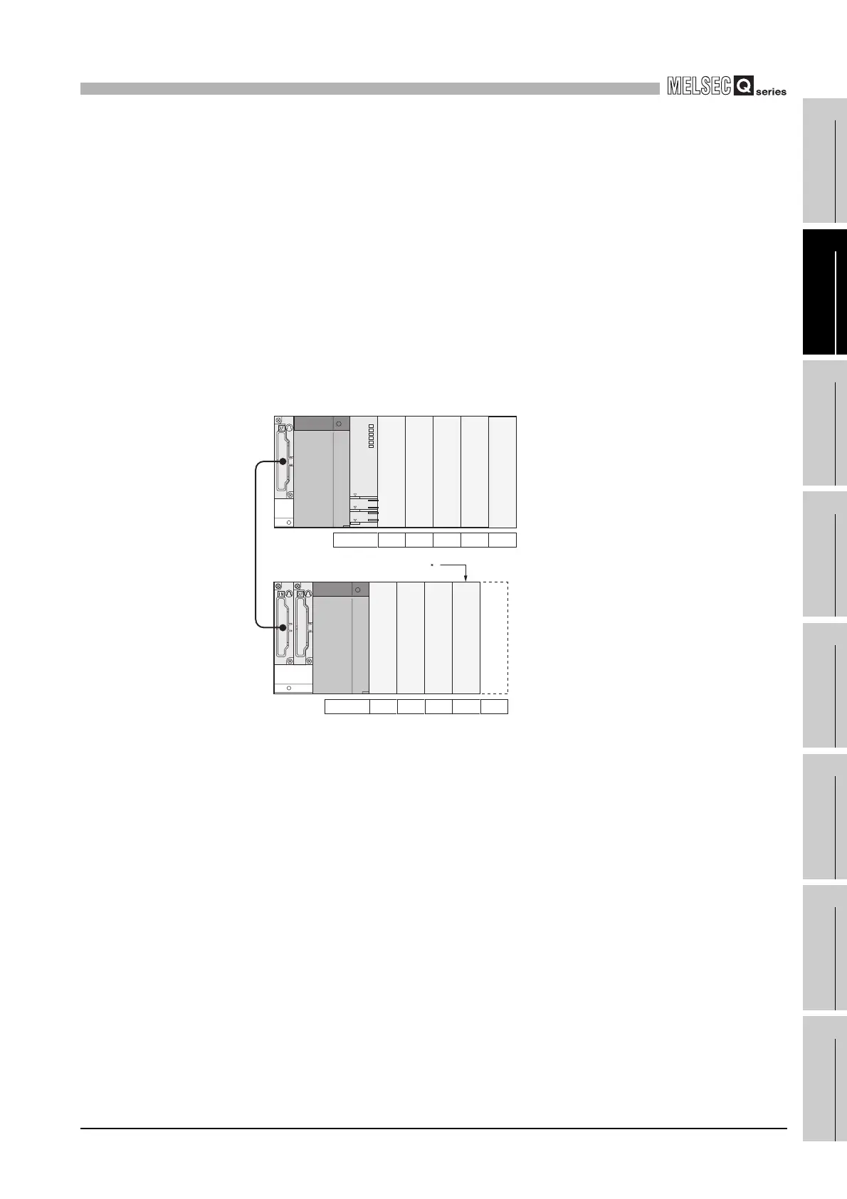
Diagram 10.3 and Diagram 10.4 are a system example and its fail-safe circuit
example.
* 1: The output module for fail-safe purpose should be loaded in the last slot of the system. (Y80 to
Y8F in the above system.)
Diagram 10.3 System example
Extension cable
Y80 to Y8F
No. of slots
Output module for fail-safe purpose 1
16 points 16 points 16 points 16 points16 points
No. of slots 16 points 16 points 16 points16 points
Input
Output
Output
Empty
Output
Output
Output
Input
Input
Input
 Loading...