10 - 18
10.3 Module Installation
10.3.1 Precaution on installation
10
LOADING AND INSTALLATION
In addition, when three or more modules with 130mm or more in depth (such as
Q66DA-G etc.) are mounted, or when the base unit is used in the environment
with extremely large vibration, use the Q6DIN1A Q-type base DIN rail mounting
adaptor (vibration-proofing bracket kit) where the large mounting bracket is
included. The large mounting bracket enables to enhance the resistance to
vibration. Depending on the environment, it is recommended to mount the base
unit on the control panel directly.
1) Q6DIN1A applicable models
Q00JCPU, Q33B, Q35B, Q38B, Q312B, Q32SB, Q33SB, Q35SB, Q38RB,
Q38DB, Q312DB, Q52B, Q55B, Q63B, Q65B, Q68B, Q612B, Q68RB,
Q65WRB
POINT
When stoppers are used, the dimension of stoppers need to be considered in the
unit installation dimensions. Refer to a CPU user’s manual for the base unit
dimensions (W).
Table10.5 Q-tyep base DIN rail mounting adaptor (Vibration-proofing bracket kit) included parts
DIN rail mounting
adaptor (Vibration-
proofing bracket kit)
Quantity of included parts
Adaptor
(Large)
Adaptor
(small)
Module
mounting
screw
(M4 10)
Square
washer
Stopper
Mounting
bracket L
Mounting
bracket R
Mounting
screw
(M5 10)
Q6DIN1A 24432113
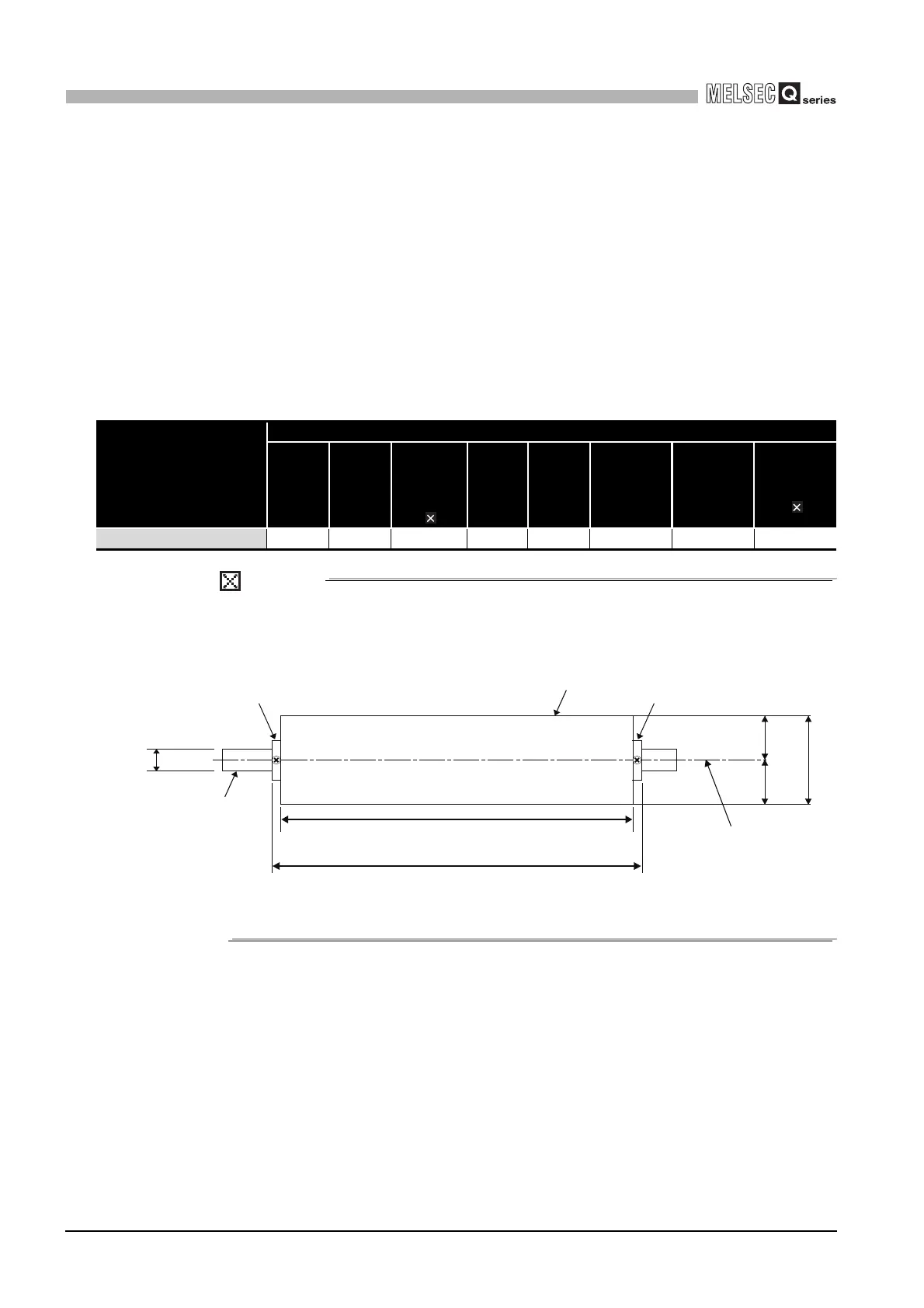
Diagram 10.16 Base unit external dimensions (Front view)
Unit: mm (inch)
49 49
Base unit
DIN rail
W+18(0.71)
Base unit width : W
DIN rail center
35(1.38)
(1.93)
98(3.86)
(1.93)
Stopper Stopper
 Loading...