App - 16
Appendix 1 External Dimensions
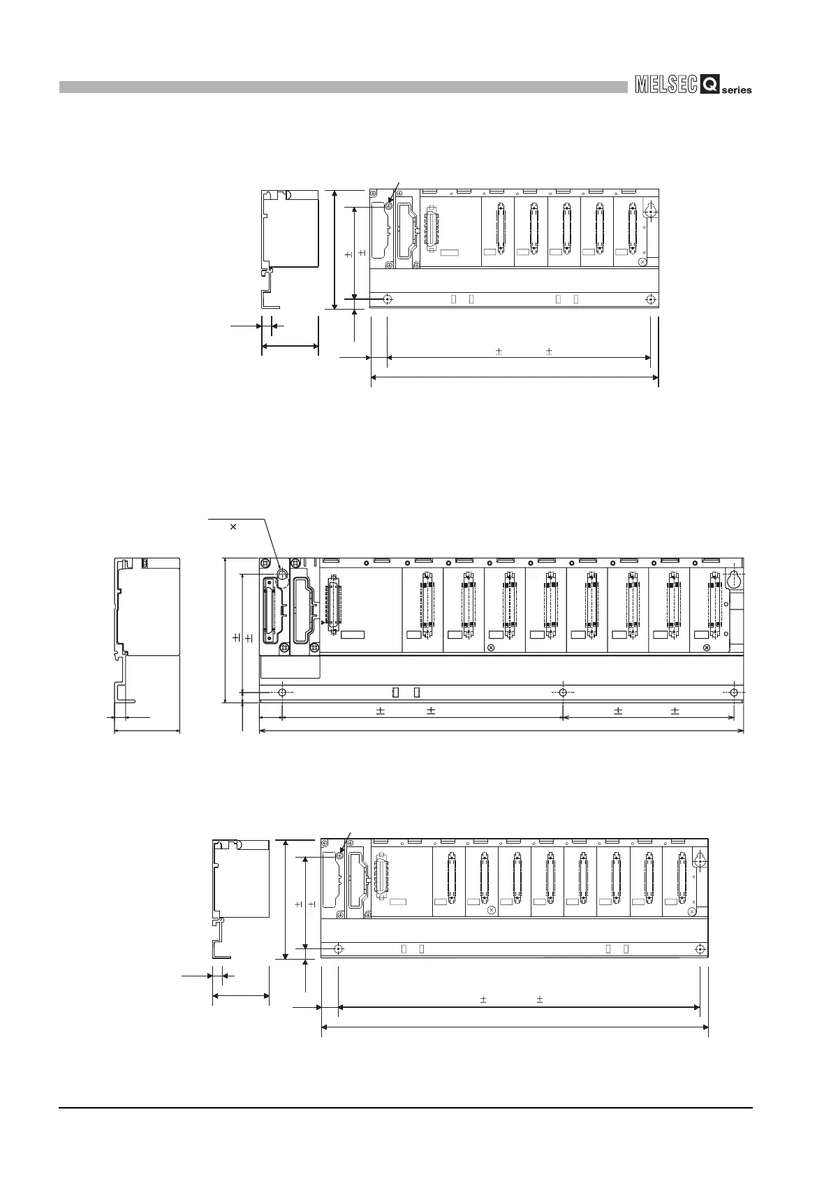
Appendix 1.4 Extension base unit
APPENDICES
(4) Q65B
(5) Q68B
(a) Q68 with 5 base mounting holes
(b) Q68 with 4 base mounting holes
Unit : mm (inch)
Diagram App.29 Q65B
Unit : mm (inch)
Diagram App.30 Q68B (5 base mounting holes)
Unit : mm (inch)
Diagram App.31 Q68B (4 base mounting holes)
I/O0
FG
I/O2I/O1 I/O3 I/O4
7.5
44.1
98 (3.86)
7
15.5
245 (9.65)
POWER
5V
SG
OUTIN
4-mounting screws (M4×14)
80 0.3
222.5 0.3 (8.76 0.01)
(0.30)
(1.74)
(0.28)
(0.61)
(3.15 0.01)
98(3.86)
80 0.3
15.5
7
b1
a1
5V
SG
FG
POWER
I/O0 I/O1 I/O2 I/O3 I/O4 I/O5 I/O6 I/O7
328(12.91)
44.1
(1.74)
7.5(0.30)
IN OUT
5-mounting screws
(M4 14)
190 0.3(7.48 0.01) 116 0.3 ( 4.57 0.01)
(3.15 0.01)
(0.28)
(0.61)
I/O2I/O1I/O0
POWER
FG
I/O5I/O4I/O3 I/O6 I/O7
7.5
44.1
98 (3.86)
7
15.5
80 0.3
328 (12.91)
5V
SG
OUTIN
4-mounting screws (M4×14)
306 0.3 (12.05 0.01)
(0.30)
(1.74)
(0.28)
(0.61)
(3.15 0.01)
 Loading...