APPENDICES
Appendix 1 External Dimensions
Appendix 1.4 Extension base unit
App - 17
9
EMC AND LOW
VOLTAGE
DIRECTIVES
10
LOADING AND
INSTALLATION
11
MAINTENANCE AND
INSPECTION
12
TROUBLESHOOTINGAPPENDICES INDEX
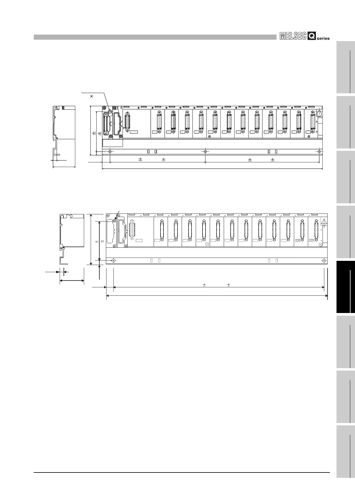
(6) Q612B
(a) Q612B with 5 base mounting holes
(b) Q612B with 4 base mounting holes
Unit : mm (inch)
Diagram App.32 Q612B (5 base mounting holes)
Unit : mm (inch)
Diagram App.33 Q612B (4 base mounting holes)
98(3.86)
439 (17.28)
7
15.5
b1
a1
5V
SG
FG
POWER
I/O0 I/O1 I/O2 I/O3 I/O4 I/O5 I/O6 I/O7 I/O8 I/O9 I/O10 I/O11
5-mounting screws
(M4 14)
IN OUT
44.1
7.5(0.30)
80 0.3
227 0.3 (8.94 0.01)
190 0.3 (7.48 0.01)
(0.28)
(3.15 0.01)
(0.61)
(1.74)
I/O9I/O8I/O7I/O6I/O5I/O4I/O3I/O2I/O1I/O0
7.5
44.1
98 (3.86)
7
15.5
439 (17.28)
POWER
FG
5V
SG
OUTIN
4-mounting screws (M4×14)
80 0.3
417 0.3 (16.42 0.01)
(0.30)
(1.74)
(0.28)
(0.61)
(3.15 0.01)
 Loading...