2
SYSTEM CONFIGURATION
2.1 System Configuration
2.1.1 System Configuration for Single CPU System
2 - 12
1
OVERVIEW
2
SYSTEM
CONFIGURATION
3
GENERAL
SPECIFICATIONS
4
HARDWARE
SPECIFICATIONS OF
THE CPU MODULE
5
POWER SUPPLY
MODULE
6
BASE UNIT AND
EXTENSION CABLE
7
MEMORY CARD AND
BATTERY
8
CPU MODULE START-
UP PROCEDURES
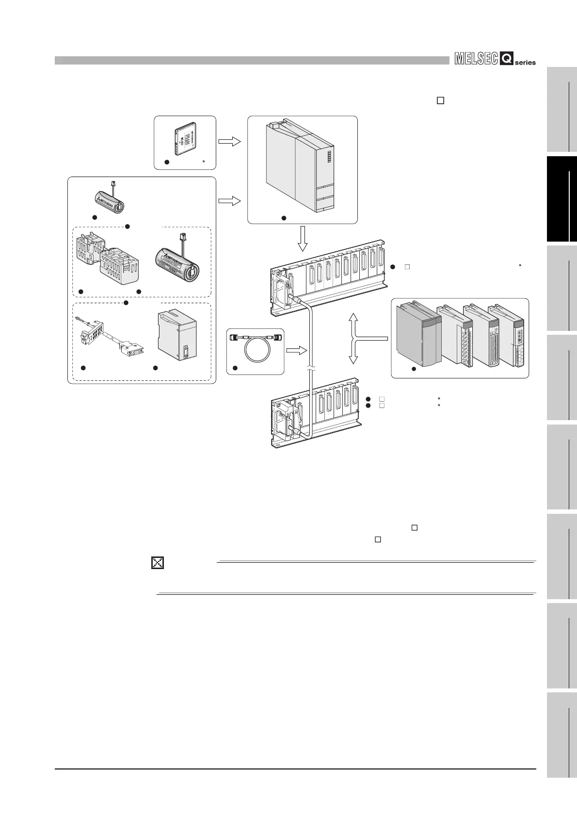
(c) When the Multiple CPU high speed main base unit (Q3 DB) is used
* 1: One memory card can be installed.
Select a memory card from SRAM card, Flash card, and ATA card according to the application
and capacity.
With commercial memory cards, the operation is not assured.
* 2: As a power supply module, use the Q series power supply module.
The slim type power supply module and the redundant power supply module are not available for
the power supply module.
* 3: The Q series power supply module is not required for the Q5 B extension base unit.
POINT
The Process CPU cannot be mounted on the slim type main base unit.
Diagram 2.11 System configuration when Q3 DB is used
Process CPU
Extension cable
Battery holder Battery for QCPU (Q7BAT)
Battery for QCPU (Q6BAT)
Q7BAT-SET
Memory card
1
Q6 B extension base unit
Q5 B extension base unit
2
3
Power supply module/I/O module/
Intelligent function module
Battery for QCPU
(Q8BAT)
Q8BAT-SET
Q8BAT connection cable
Q3 DB multiple CPU high speed main base unit
2
 Loading...