2 - 29
2.1 System Configuration
2.1.2 System Configuration for Bus connection of GOT
2
SYSTEM CONFIGURATION
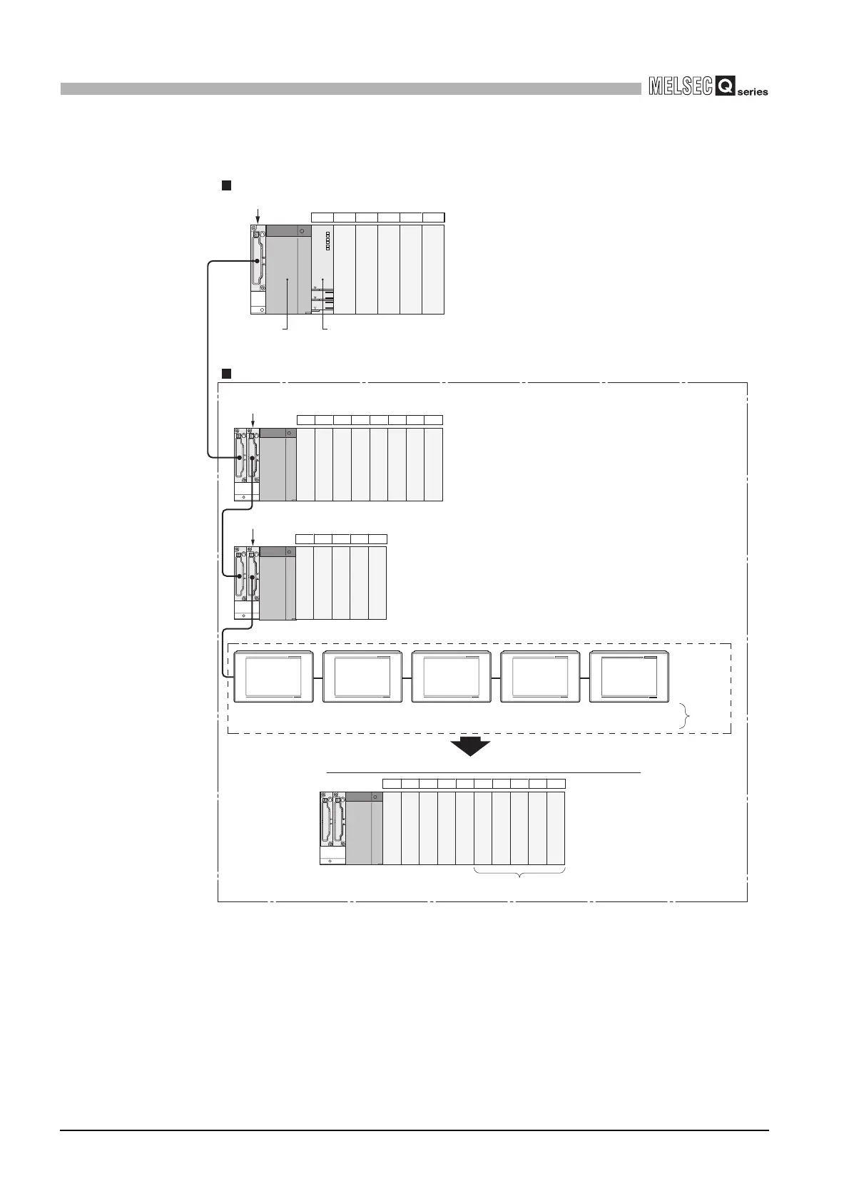
(4) Outline of system configuration
Diagram 2.23 System configuration example when using GOT
CPU module
Q35B (5 slots occupied)
Q68B (8 slots occupied)
Q65B (5 slots occupied)
00 to 0F
10 to 1F
20 to 2F
30 to 3F
40 to 4F
50 to 5F
60 to 6F
70 to 7F
80 to 8F
90 to 9F
A0 to AF
B0 to BF
C0 to CF
D0 to 0F
E0 to EF
F0 to FF
100 to 10F
110 to 11F
CPU 0 1 2 3 4
5 6 7 8 9 101112
13 14 15 16 17
Q series
power supply
module
No. of extension stages: 3
slots No.: 0
Stage extension image for GOT connection viewed from CPU module
120 to 12F
130 to 13F
140 to 14F
150 to 15F
160 to 16F
18 19 20 21 22 23 24 25 26 27
1) 2) 3) 4) 5)
1) 2) 3) 4) 5)
No. of extension stages: 3
slots No.: 1
No. of extension stages: 3
slots No.: 2
No. of extension stages: 3
slots No.: 3
No. of extension stages: 3
slots No.: 4
Set on
the GOT
side.
Set to empty in "I/O assignment setting"
of PLC parameter
GOT (No. of extension stages:F3)
16 points ×10 slots occupied
Main base unit The figure shows the configuration when 16-point modules are loaded to each slot.
...
Extension base unit The figure shows the configuration when 16-point modules are loaded to each slot.
...
....
....
I/O number
Slot number
 Loading...