2-10
2 Robot arm
2.2.2 Rated load (mass capacity)
The robot's mass capacity is expressed solely in terms of mass, but even for tools and works of similar mass,
eccentric loads will have some restrictions When designing the tooling or when selecting a robot, consider the fol
-
lowing issues.
(1) The tooling should have the value less or equal than the smaller of the tolerable inertia and the tolerable
moment found in Page 8, "2.1.1 Basic specifications".
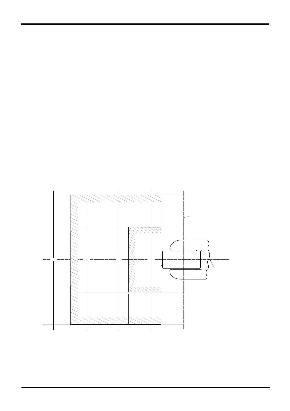
(2) Fig. 2-1 shows the distribution dimensions for the center of gravity in the case where the volume of the
load is relatively small. Use this figure as a reference when designing the tooling.
(3) Even if the load is force, not the mass, design the tooling so that moment does not exceed the allowable
moment. Refer to Page 8, "Table 2-1 : Standard specifications of robot" for details of allowable moment
value.
[Caution] The mass capacity is greatly influenced by the operating speed of the robot and the motion posture.
Even if you are within the allowable range mentioned previously, an overload or generate an overcurrnt
alarm could occur. In such cases, it will be necessary to change the time setting for acceleration/deceler
-
ation, the operating speed, and the motion posture.
[Caution] The overhang amount of the load, such as the mass capacity and the allowable moment of inertia
defined in this section, are dynamic limit values determined by the capacity of the motor that drives axes
or the capacity of the speed reducer. Therefore, it does not guarantee the accuracy on all areas of tooling.
Guaranteed accuracy is measured from the center point of the mechanical interface surface. Please note
that if the point of operation is kept away from the mechanical interface surface by long and low-rigid
tooling, the positioning accuracy may deteriorate or may cause vibration.
[Caution] Even within the allowable range previously mentioned, an overload alarm may be generated if an ascend
-
ing operation continues at a micro-low speed. In such a case, it is necessary to increase the ascending
speed.
Fig.2-1 : Position of center of gravity for loads (for loads with comparatively small volume)
200
200
0
単位 : mm
J6軸回転中心
J5軸回転中心
100
2.0kg
100
100
400
170350
70
1.0kg
200
300
Unit: mm
J5 axis rotation center
J6 axis rotation center
 Loading...


