2 Robot arm
Tooling 2-17
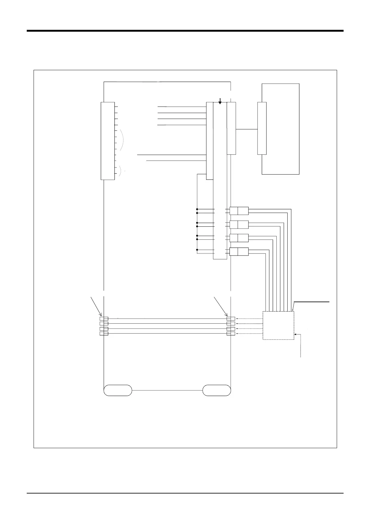
2.5.5 Wiring and piping system diagram for hand
Shows the wiring and piping configuration for a standard-equipped hand.
Fig.2-6 : Wiring and piping system diagram for hand and example the solenoid valve installation (Sink type)
<ハンドチェック 1>
<
ハ
ンドチェック
2>
<
ハ
ンドチェック
3>
<
ハ
ンドチェック
4>
<+24V>
<0
V
(COM
)>
A1
A2
A3
A4
A5
A6
B1
B2
ロボット
コントローラ
電磁弁の
ソレノイド部
電磁弁
マニホールド
電磁弁
セット
(オプション)
取付部
AIR IN1
AIR IN2
AIR IN3
AIR IN4
(φ6ホース)
φ4ホース(4本)
φ4クイック継手渡
し
(1~4
)
AIR OUT1
AIR OUT2
AIR OUT3
AIR OUT4
リスト部
ベース部
900
+24V
901
+24V
902
+24V
903
+24V
GR1
GR2
GR3
GR4
1
2
1
2
1
2
1
2
B3
1次エアー
供給口
へ
接続
汎用入力
900
汎用入力
901
汎用入力
902
汎用入力
903
B4
B5
B6
予約
φ4クイック継手渡
し
(1~4
)
予約
Refer to Fig. 2-8 for air supply
circuit example.
<Hand check 1>
<Hand check 2>
<Hand check 3>
<Hand check 4>
General-purpose
input No.
900
901
902
903
General-purpose
input No.
Robot
controller
φ4 quick coupling bridge(1 to 4)
φ4 quick coupling bridge(1 to 4)
φ4 hose(4 hoses)
Solenoid valve
installation
section
(optional)
Solenoid valve
section
Solenoid valve
manifold
Connect to
the primary
air supply
(φ6 hose)
Base section
Wrist section
Reserve
Reserve

 Loading...


