2 Robot arm
2-11
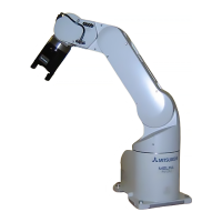
2.2.3 Vibrations at the Tip of the Arm during Low-Speed Operation of the Robot
Vibrations at the tip of the arm may increase substantially during the low-speed operation of the robot, depending
on the combination of robot operation, hand mass and hand inertia. This problem occurs when the vibration count
specific to the robot arm and the vibration count of the arm driving force are coming close to each other. These
vibrations at the tip of the arm can be reduced by taking the following measures:
1) Lower the robot's operating speed by approximately 5% from high speed using the Ovrd command.
2) Change and move the teaching points of the robot.
3) Change the hand mass and hand inertia.
2.2.4 Collision detection
This series have the "collision detection function" which detects the abnormalities by the collision of the robot
arm, however initial setting is in invalid condition.
The enable/disable of this function can be changed by parameter: COL and command: ColChk, this function is
effective for protect of the robot and of the peripheral equipment.
The abnormalities are detected by the robot's kinetics model, presuming torque necessary for movement at any
time. Therefore, the setting parameter (HNDDAT*, WRKDAT*) of the hand and the work piece conditions should
be right. And, it may be detected as the collision in movement as speed and motor torque are changed rapidly. (for
example, the movement near the place of the origin by linear interpolation, the reversal movement, the cold condi
-
tion, the operation after long term stoppage)
In such a case, by adjusting the value of the setting parameter (COLLVL, COLLVLJG) of the collision detection
level according to actual use environment, the sensitivity of collision detection can be optimized and the damage
risk can be reduced further. And, in the operation after the low temperature or long term stoppage, please operate
by accustoming at low speed (warm-up), or use the warm-up operation mode.
Refer to the separate instruction manual "Detailed explanations of functions and operations" for details of related
parameter.
Table 2-2 : Factory-shipments condition
2.2.5 Protection specifications
(1) Types of protection specifications
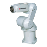
The robot arm has protection specifications that comply with the IEC Standards. The protection specifications
and applicable fields are shown in Table 2-3.
Table 2-3 : Protection specifications and applicable fields
The IEC IP symbols define the degree of protection against solids and fluids, and do not indicate a protective
structure against the entry of oil or water.
The IEC standard is described by the following "Information" And, the corrosion of the rust etc. may occur to the
robot with the liquids, such as the water and the oil.
【Information】
・ The IEC IP30
The protection standard for approach in the dangerous spot in the tool. It indicates the protective structure
that the proximity probe 2.5mm in diameter must not advance.
JOG operation Automatic
RH-2F series Invalid Invalid
Type
Protection
specifications
(IEC Standards value)
Classification Applicable field Remarks
RV-2F series Robot arm: IP30
(all axes)
General environ
-
ment specifications
General assembly
Slightly dusty environment
 Loading...
