3 Controller
Names of each part 3-39
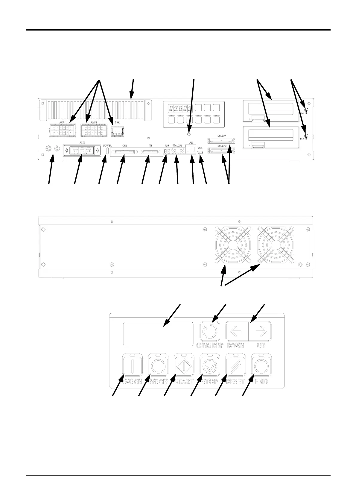
(2) CR751 controller
Fig.3-2 : Names of controller parts (CR751)
<1> ACIN connector.......................................The connector for AC power source (1-phase, AC200V) input (a socket
housing and a terminal are attached)
<2> PE terminal ................................................The screw for grounding of the cable. (M4 screw x 2 place)
<3> POWER lamp.............................................Lamp of control power source
<4> Machine cable connector (motor power)
AMP1, AMP2: Motor power, BRK: Motor brake
<2> <1> <3>
<4> <7> <15> <9>
<5> <6> <14> <13> <12><11> <8>
<10>
Controller (Front side)
Exhaust
Controller (Rear side)
<15>: The operation panel
<18>
<19> <20> <21> <22> <23> <24>
<17><16>
 Loading...


