10
2 Setup for Mounting
No. 99MBE095B
2.4
Precautions on Mounting Design of Scale Unit
The following describes some design points regarding the "mounting surface" for installing the scale
unit onto the machine.
In addition, refer to
"4.6 External View and Dimensional Drawings of the Scale Main Unit".
2.4.1 Datum Point Position for the Length Variation and ABS Origin
Point
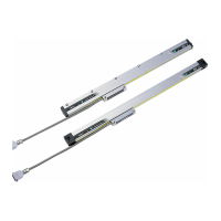
The xing parts of the scale unit are divided into the full-xing parts and the elastic xing parts.
The "datum point position for length variation", which represents the reference point for the scale’s
mechanical expansions and contractions due to changes in temperature, is shown below.
Note with caution that users are not able to change this datum point position.
The internal electrical "ABS origin point" is set at 20 mm left from the edge of the eective length.
Elastic xing parts
Full-xing part
Elastic xing parts
ABS origin point
Datum point position
for length variation
(20 mm left from the eective length)
(20)
Full-xing part
Tips
• The quantity of the elastic xing parts is dierent depending on the eective length.
• The elastic xing parts cannot be moved horizontally.
• The system's overall temperature characteristics are stabilized by setting the behavior of the center posi-
tion in regard to the machine unit's temperature change and the scale unit’s datum point position for length
variation closer.
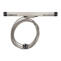
2.4.2 Counting Direction
When the detector head is moved rightward in the diagram below, the output serial data will increase
the count (i.e., to the + side).
Data "20" position
(Left edge of eective
length)
Serial data increments
Scale unit
 Loading...