38
4Specications
No. 99MBE095B
4.6
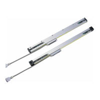
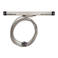
External View and Dimensional Drawings of the
Scale Main Unit
4.6.1 External View and Dimensional Drawings
9
7
76
±0.2
25
±0.2
L
5
(L
4
=(L
0
/2)+65)
Effective length L
0
Maximum moving amount L
1
* Opposite side of
mounting surface
Total length L
2
=L
0
+119
62.5
35
6
62
±0.2
X
58.5
P100±0.2
P100×n
L
3
=(L
0
/2)+30:Recommended
Arrow view of "Y"
(n+2or3)-ø7 through hole
A
B
C
Signal cable
connecting
direction can be
changed.
94
40±0.2
(20)
(45)
2-ø7
Hex (both sides), depth 6.5
M6x1.0 length 40
ø6.5
ABS origin point
Signal cable assembly
Datum point position for the length
2-M5, depth 5
M5 screwM6 nut
Aluminum frame
SUS bushing
Special plate spring
M6x30 + Small round
plain washer
Fixing example 2
Fixing example 3
* The dimensions of the installation
gap are different between the front
and the back side depending on the
gradient of the Detector head.
(1.5)
2 ± 0.2
(gap between Detector
head and aluminum frame)
25
24.5
(gap between Detector head
and aluminum frame)
Longitudinal
direction
Air purge
M5x0.8, depth 5
(both directions)
□Arrow view of "X"
Fixing example 1
2±0.1
0.1 R
P
0.1
P
85
17.2
12.5
24
19
41.8
37
CBA
For three holes: fix at two points of A and C (recommended)
For two holes: fix at two points of the both holes
・ Check the scale main unit mounting dimensions with the
head fixing blocks attached.
・ The number of the holes at the full-fixing part is different
depending on the total length of the scale.
For details, see the table below.
Full-xing part
 Loading...