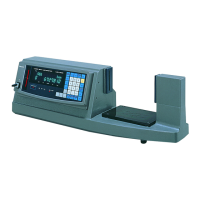
▲ Control Panel
Control/Display Unit
Switch
Switch Description
(1) Up Moves the spindle up only while the switch is pressed down.
(2) Down
Moves the spindle down only while the switch is pressed down.
It is used when the contact point is brought into contact with a workpiece. (Use it at
measurement.)
(3) Quick Up Quickly moves the spindle up only while the switch is pressed down.
(4) Quick Down Quickly moves the spindle down only while the switch is pressed down.
(5) ZERO
Sets the origin at any given point. Also, it zero-sets all display values at runout
measurement. This switch can be used to clear an error.
(6) PRESET
Allows the origin to be set at any given height by entering it beforehand. To set the
origin, use a standard specimen given the correct actual dimension, such as a
gauge block.
(7) MODE
Used to select and set one of various measurement modes such as MAX/MIN
measurement.
(8) LIMIT Used to enter tolerance limits for tolerance judgment.
(9) TEACH Used to set up the position memory.
(10) PM1 to PM3
Used to move the spindle to an arbitrary position that has been stored with a single
keystroke.
Indicator (LED)
Indicator Description
(11) GO/NG Displays the result of GO/NG judgment.
(12) Sign Lights to display a minus value. (for a maximum digit of number)
(13) MAX Lights in the maximum value mode.
(14) MIN Lights in the minimum value mode.
(15) WORK Lights while a workpiece is being detected.
(16) T.H. Lights up when a measured value is held after measurement has been completed.
(17) C.T.
Lights up when the user compensation is set to ON. (Lights while the position
memory is active.)
(18) UNIT
Lights while the unit of display values is in 1/25.4 mm. (Lights in the external HOLD
mode.)
No. 99MBC082B
3 - 6
 Loading...