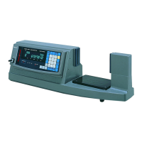
PRINT OUTPUT FUNCTION
Print output function allows printout using Digimatic Mini Processor
DP-1VR. Follow the procedure below for the setup.
7
Perform the following setups before making cable connection.
(1) Setup on the VL side
S
“
et parameter No.23 (Output selection) to 1 (Digimatic), and then turn on the power again. (Refer to
3.SETTING UP”.)
(2) Setup on the printer side
• Change the printer setup from the interface mode to the compatible mode.
Key operation Response display/output Description
1
While holding down
[ZERO], press [CE]
INTERFACE: ADVANCE
While holding down the [CE] key press the [POWER] key.
The currently-set mode is printed.
2 Press [STAT]. INTERFACE: COMPATIBLE
If the interface mode is “ADVANCE”, press the [STAT] key to enter
the COMPATIBLE mode.
3 Press [DATA]. Data input mode
Press the [DATA] key to enter the data input mode.
(3) Cable connection
C
V
P
P
I
I
I
p
onnect the cable to the following connectors.
L side: OUT connector
rinter side: INPUT connector
(4) Print
ress the [DATA] key on the printer to print a display value.
f a display value exceeds 6 digits, the lower 6-digit value is printed.
f parameter No.15 has been set to 1, the lower 6-digit value without a decimal point is printed.
f parameter No.36 has been set to 1 and parameter No.28 has been set up to 2, printout is automatically
erformed when the spindle comes into contact with a workpiece.
IMORTANT
Pay attention to each connector orientation. A protrusion is mounted on the upper side of
both VL and printer connectors.
Reverse insertion will result in damage to the connectors.
No. 99MBC082B
7 - 1
 Loading...