CHAPTER 3: USING UNIFLOW
®
2 PROGRAMMING FUNCTIONS
UNIFLOW
®
2 PULSED THERMODE CONTROL
3-8 990-228
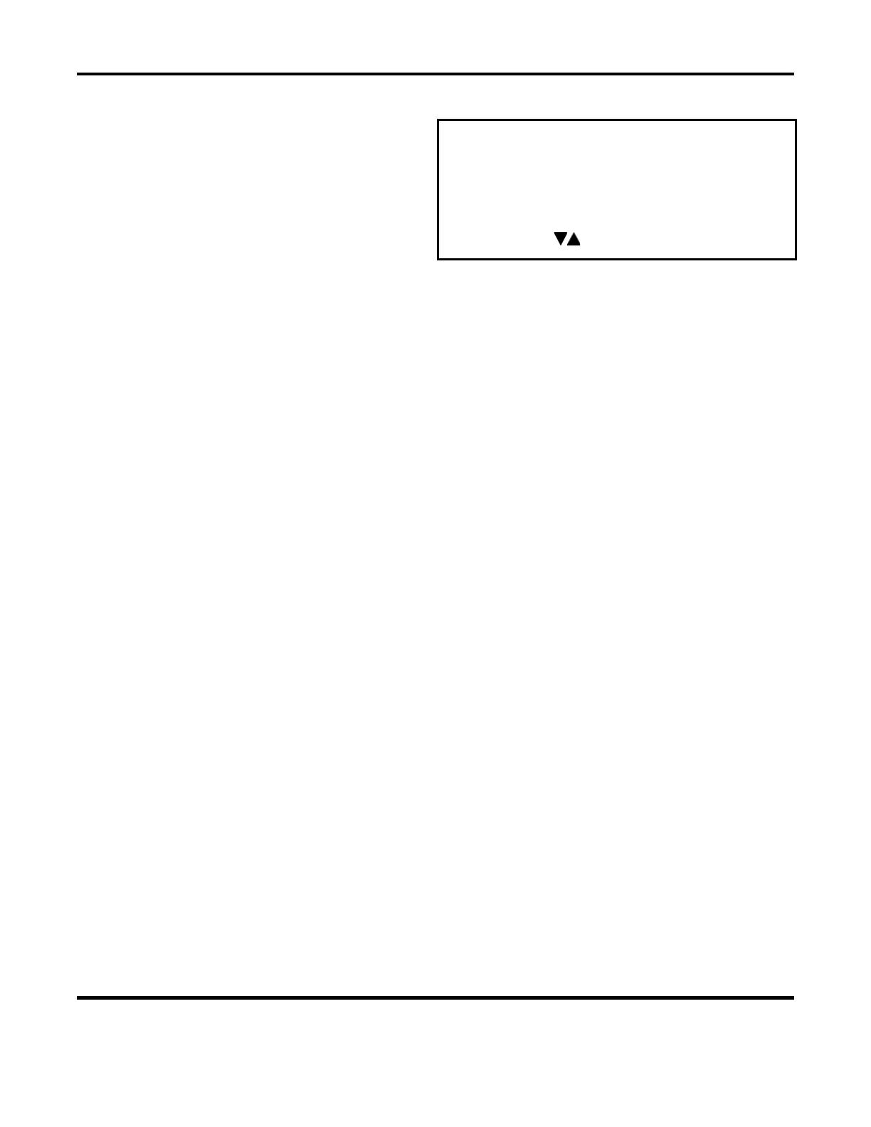
HARDWARE SETUP, Page 1
Pressing
1 with the SETUP MENU screen
displayed will bring up Page 1 of the
HARDWARE SETUP screen.
< HARDWARE SETUP, page 1 of 2 >
1. HEAD COOL VALVE IS : OFF
2. SOLDER COOL VALVE IS : OFF
3. FOOTSWITCH RESPONSE MODE : ABORT
4. LIST OF HARDWARE
NUMBER Select,
Page, Graph or Data
HEAD COOL VALVE IS, Page 1
Press the 1 key to toggle between OFF and ON. Selecting ON continuously activates the head cool
valve, which supplies drive power for a user-supplied air solenoid valve. The drive power is
connector-selectable at either 24 VAC or +24 VDC
NOTE: If Preheat is turned
ON, the head cool valve is automatically turned on. This valve controls
air to cool a hot thermode holder on a reflow solder or heat seal head. See Appendix B, Electrical
and Data Connections for connection details.
SOLDER COOL VALVE IS, Page 1
Press the 2 key to toggle between OFF and ON. Selecting ON will activate the solder cool valve
starting at the end of the
Heat period and de-activating when the thermode reaches the Cool
temperature. The solder cool valve is used to direct the cool air onto the thermode to force it to cool
faster. The solder cool valve supplies a connector-selectable 24 VAC or +24 VDC signal for
controlling a user supplied air solenoid valve.
FOOTSWITCH RESPONSE MODE, Page 1
Press the
3 key toggle between ABORT and LATCH. This will deselect and select how the foot switch
initiates a Control process cycle when an air actuated head is used.
Use ABORT when employing an operator to position parts. Releasing the foot switch at any time during
the heating cycle immediately turns off thermode heating and retracts the thermode from the surface of
the parts.
Use
LATCH with automated or fixtured applications. Once the second level of a 2-level foot switch is
activated, the heating cycle will continue to completion unless the EMERGENCY STOP switch is
actuated.
 Loading...