CHAPTER 3: USING UNIFLOW
®
2 PROGRAMMING FUNCTIONS
UNIFLOW
®
2 PULSED THERMODE CONTROL
990-228 3-13
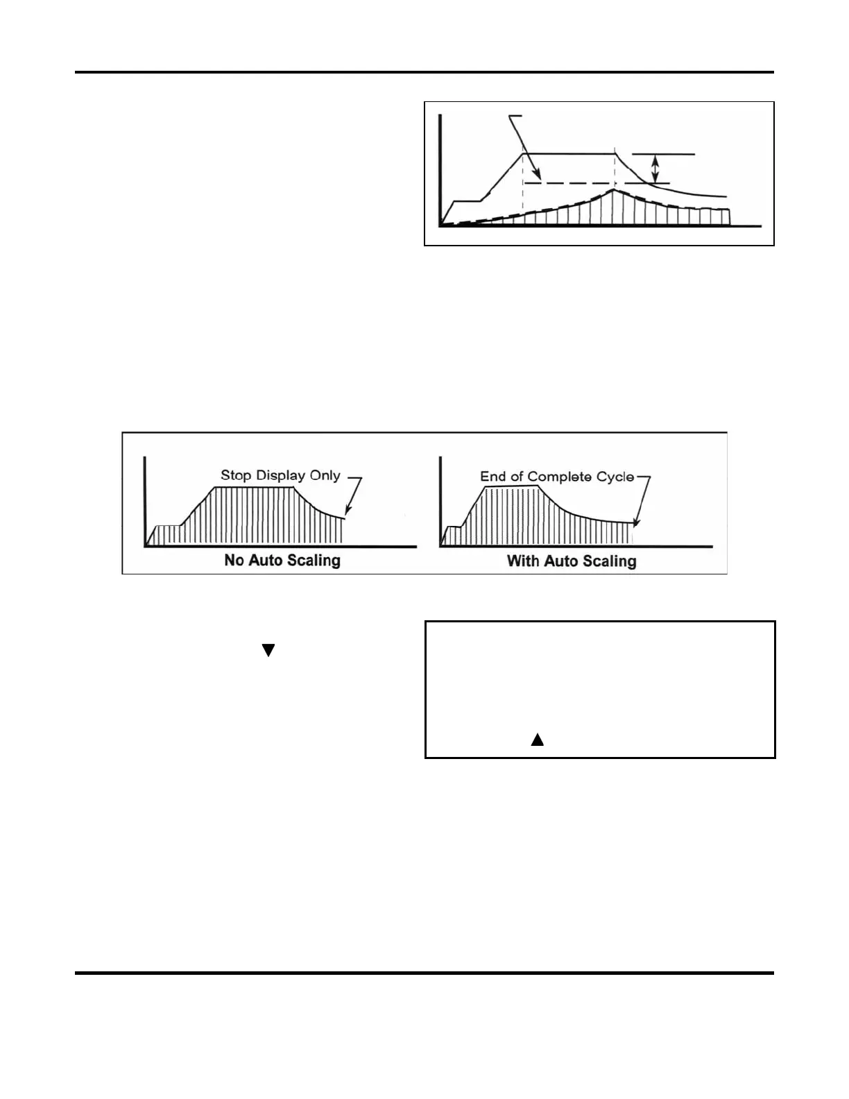
The Lower Temperature Limit only covers the
Reflow period as shown on the right. The actual
temperature must be above the lower
temperature limit by the end of the Reflow
period to avoid triggering the alarm. Going
below the
Lower Temperature Limit, as shown by
the dashed temperature curve, does not terminate
Lower Temperature Limit
-50
C
thermode heating or retract the thermode from
the parts, but it does produce an alarm.
AUTOSCALING FEATURE:
Press the 4 key to toggle between OFF and ON.
Selecting
OFF means that the actual graphic temperature display will fill in over the Ideal Profile on the
screen until the fill reaches the end of the display.
Selecting ON causes the graphic display to automatically re-scale at Cool time to capture more of the
reflow , including a longer portion of the cooling cycle.
REFLOW TEMPERATURE SETUP, Page 2.
From the
REFLOW TEMPERATURE SETUP page
1
screen showing, press the key to bring up the
REFLOW TEMPERATURE SETUP page 2 screen.
< REFLOW TEMPERATURE SETUP, page 2 of 2 >
1. SET SAFETY TIMER : 10 SEC
2. SET RELEASE TIMER : 00 SEC
3. MAX. TEMPERATURE LIMIT : 600
C
4. MAX IDLE TEMP LIMIT : 500
C
Number Select
Page, Graph or Data
 Loading...