CHAPTER 2: INSTALLATION AND SETUP
UNIFLOW
®
2 PULSED THERMODE CONTROL
2-6 990-228
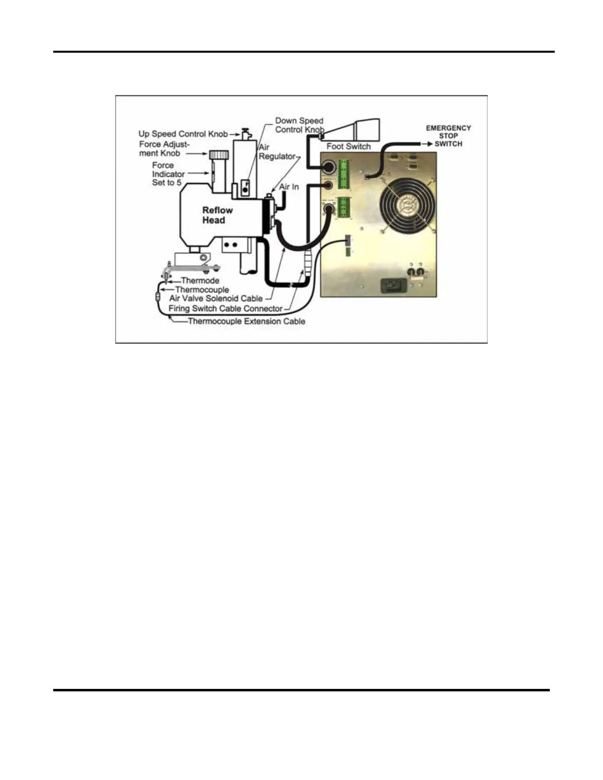
Force Fired, Air Actuated Head
1. Adjust the head force adjustment knob to produce 5 units of force, as displayed on the force
indicator index.
2. Connect the head firing switch cable connector to the Control firing switch
INITIATE cable
connector.
3. Remove the
EMO jumper on connector EMO, pins 1 and 2 on the Control rear panel.
4. Connect a normally closed, CE approved, emergency stop switch to connector EMO, pins 1
and 2 on the Control rear panel. (See Appendix B, Electrical and Data Connections for more
details.) When this switch is operated (open), it will immediately stop the heating cycle and
retract the thermode from the parts.
NOTE: If Connector EMO, Pins 1 and 2, on the rear panel are not shorted, either by an EMO
switch or the jumper plug, this screen will include the message:
NOTE: EMO JUMPER NOT
INSTALLED
.
5. Using the air-head manufacturer’s user manual for reference, connect the head air valve
solenoid cable connector to the Control HEAD VALVE connector.
NOTE: This connector supplies 24 VDC or 24 VAC power only -- it will not drive 115 VAC
air valves.
 Loading...