Installation
Micro-Ion
®
Module Instruction Manual - 356007-GP 21
Installation Operation MaintenanceBefore You Begin
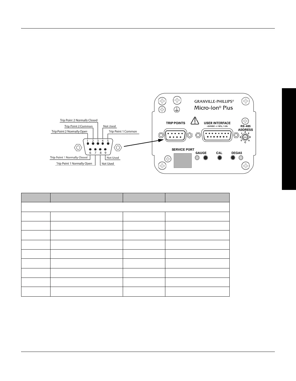
Relay Wiring The module has two trip point relays. The contacts are silver alloy-gold
clad, rated for 1 A at 30 Vdc. The relays can handle resistive or
non-inductive loads.
• Figure 2-6 illustrates the 9-pin trip point connector.
• Table 2-3 lists pin connections for the 9-pin male D connector.
Figure 2-6 Trip Point Relay 9-pin Connector
Table 2-3 Trip Point Relay 9-pin Connector Pins
Pin # Function Input/Output Voltage Level
These voltage levels apply ONLY for resistive or non-inductive loads.
Pin 1 Relay 2: Normally open Output 0 to 30 Vdc, 1 A
Pin 2 Relay 2: Common Output 0 to 30 Vdc, 1 A
Pin 3 Relay 2: Normally closed Output 0 to 30 Vdc, 1 A
Pin 4 Not used No connection
Pin 5 Relay 1: Common Output 0 to 30 Vdc, 1 A
Pin 6 Relay 1: Normally closed Output 0 to 30 Vdc, 1 A
Pin 7 Relay 1: Normally open Output 0 to 30 Vdc, 1 A
Pin 8 Not used No connection
Pin 9 Not used No connection

 Loading...

