Chapter 3
38 Micro-Ion
®
Module Instruction Manual - 356007-GP
Relay Configuration using
Trip Point Buttons and
LEDs
1. Make sure the module is properly installed and power is ON.
2. Use the optional display LEDs and recessed interface buttons to
configure trip points. Use the trip points select button to activate the
configuration mode and select the desired trip point for configuration.
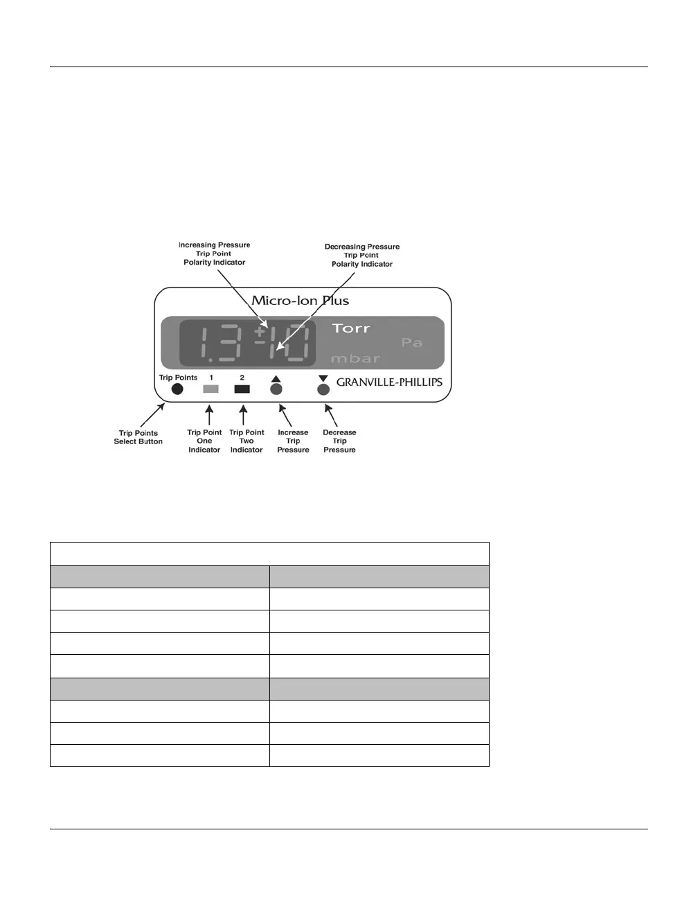
Figure 3-11 illustrates the trip point buttons and LEDs. The
corresponding LED flashes to indicate the selected trip point.
Figure 3-11 Trip Point Buttons and LEDs
Table 3-6 indicates the status of trip point indicators during operation and
configuration of trip point 1 or trip point 2.
Table 3-6 Trip Point Indicator Status
Trip Point 1 Indicator
State Trip Point 1 Indicator
Trip point relay 1 activated Solid green
Trip point relay 1 deactivated OFF
Trip point 1 configuration mode Flashing green
Trip Point 2 Indicator
State Trip Point 2 Indicator
Trip point relay 2 activated Solid green
Trip point relay 2 deactivated OFF
Trip point 2 configuration mode Flashing green

 Loading...

