10
q 3) While holding the vertical stabilizer firmly
in place, use a pen and draw a line on each side of
the vertical stabilizer where it meets the top of the
fuselage.
q 4) Remove the stabilizer. Using a modeling
knife, remove the covering from below the lines you
drew. Also remove the covering from the bottom
edge of the stabilizer, the front edge of the stabilizer
post and the rear edge of the fuselage. See photo #
13 below.
Photo # 13
When cutting through the covering to remove
it, cut with only enough pressure to only cut
through the covering itself. Cutting into the balsa
structure may weaken it.
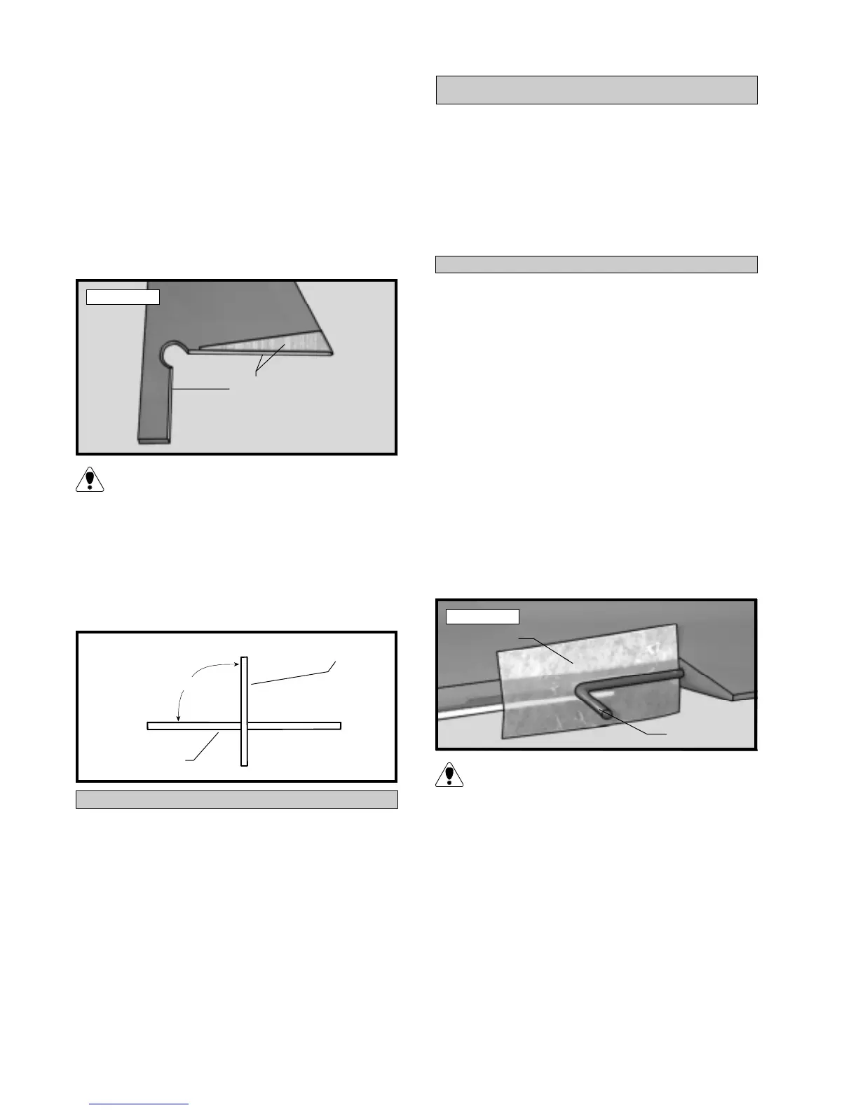
q 5) Slide the vertical stabilizer back in place.
Using a triangle, check to ensure that the vertical sta-
bilizer is aligned 90º to the horizontal stabilizer. See
figure # 4 below.
Figure # 4
MOUNTING THE VERTICAL STABILIZER
q 6) When you are sure that everything is aligned
correctly, mix up a generous amount of Kwik Bond 30
Minute Epoxy. Apply a thin layer to the mounting slot
in the top of the fuselage and to the sides and bottom of
the vertical stabilizer mounting area. Apply epoxy to
the front edge of the stabilizer post and to the rear edge
of the fuselage also. Set the stabilizer in place and
realign. Double check all of your measurements once
more before the epoxy cures. Hold the stabilizer in place
with T-pins or masking tape and remove any excess
epoxy using a paper towel and rubbing alcohol. Al-
low the epoxy to fully cure before proceeding.
q 1) The C/A hinges have already been glued into
the two ailerons. Working with one aileron at a time,
slide the aileron and it's hinges into their precut hinge
slots in the trailing edge of the wing, making sure the
torque rod is firmly seated in the precut hole in the
leading edge of the aileron. Slide the aileron in until
it is tight against the trailing edge of the wing. The
maximum hinge gap should be no more than 1/32”.
q 2) When satisfied with the fit, remove the aile-
ron. Using a modeling knife, carefully remove any
excess covering material that may have overlapped
onto the hinges. Do not cut through the hinges!
q 3) Slide a small piece of waxed paper between
the aileron torque rod and the trailing edge of the wing.
See photo # 14 below.
PARTS REQUIRED
q {1} Wing w/Ailerons & Hinges
q {1} Vertical Stabilizer w/Rudder & Hinges
q {1} Tail Wheel Assembly
q {1} 25mm Diameter Tail Wheel
q {1} 2mm Wheel Collar
q {1} 3mm x 6mm Machine Screw
q {2} 3mm x 12mm Wood Screws
CONTROL SURFACE HINGING
HINGING THE AILERONS
Photo # 14
The waxed paper will prevent epoxy from glu-
ing the torque rod to the trailing edge of the wing.
q 4) Mix up a small amount of Kwik Bond 30
Minute Epoxy. Apply a thin layer of epoxy to the
aileron torque rod. Also, use a toothpick and pack
epoxy into the predrilled hole in the aileron.
q 5) Slide the aileron and it's hinges into their pre-
cut hinge slots in the trailing edge of the wing, making
sure the torque rod is firmly seated in the predrilled
hole in the leading edge of the aileron. With the aile-
ron tight against the wing, rotate the aileron down about
45º. Apply six drops of Kwik Bond Thin C/A to the
exposed area of each hinge. Allow the glue to
Remove
Covering
Waxed Paper
Torque Rod
90º
Horizontal Stabilizer
Vertical Stabilizer