16
q 5) Test fit the throttle servo in the preinstalled
servo tray behind the forward bulkhead. The servo
should be mounted with the output shaft towards the
right side of the airplane.
Because the size of servos differ, you may need
to adjust the size of the precut opening.
q 6) Install the throttle servo using the wood
screws provided with your radio system. Drill 1/16”
pilot holes through the tray before installing the
screws. This will help prevent the wood from split-
ting. See photo # 31 below.
Photo # 31
INSTALLING THE AILERON SERVO PLATES
q 7) Test fit the aileron servo into the prebuilt servo
box in the bottom side of the wing. The output shaft
should point towards the trailing edge of the wing.
Because the size of servos differ, you may need
to adjust the size of the box opening. You may
also need to use a modeling knife and cut a groove in
one end of the box to allow room for the servo wire to
fit without kinking.
q 8) Remove the servo. Using Kwik Bond Thick
C/A, laminate two of the aileron servo mounting plates
W-24 together, making sure all four edges are flush.
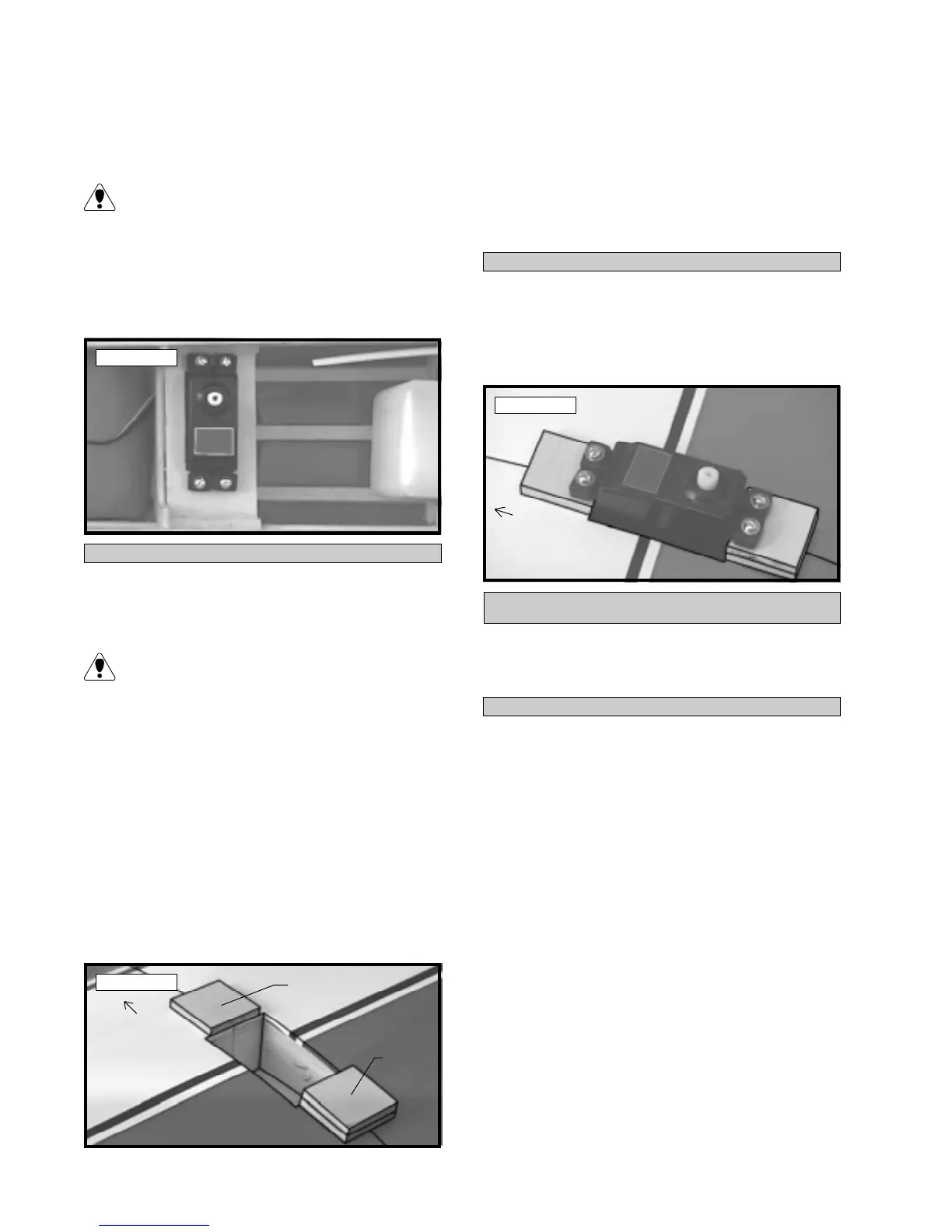
q 9) Position the servo mounting plates onto the
wing. The single plate goes at the front of the servo
opening and the laminated plate goes at the rear of
the opening. Both plates should be centered from
side to side and the inside edges should be even with
the servo opening. See photo # 32 below.
Photo # 32
q 10) Hold the two plates in position and trace
around them using a pen. Remove the plates and us-
ing a modeling knife, remove the covering from just
inside the lines.
q 11) Mix a small amount of Kwik Bond 5 Minute
Epoxy and glue the plates in place. Allow the epoxy
to cure completely.
INSTALLING THE AILERON SERVO
q 12) Install the aileron servo using the wood
screws provided with your radio system. Drill 1/16”
pilot holes through the plates before installing the
screws. This will help prevent the wood from split-
ting. See photo # 33 below.
Photo # 33
PARTS REQUIRED
q {1} 1.5mm x 45mm Threaded Wire
q {1} Nylon Clevis w/1.5mm I.D. Hole
THROTTLE CONNECTION
INSTALLING THE THROTTLE CLEVIS
q 1) With the servos plugged into the receiver, turn
on the radio system. Check to ensure that the throttle
servo output shaft is moving in the correct direction.
It should move clockwise when you advance the
throttle stick.
q 2) Position the throttle stick and the throttle trim
at their lowest positions. Thread the 1.5mm x 45mm
thread wire into the nylon throttle pushrod that was
installed previously. Thread the wire in about 5/16”.
q 3) While holding the wire with pliers, to pre-
vent it from turning, thread the nylon clevis onto the
end of the wire. Thread the clevis on about 5/16”.
q 4) Manually push the carburetor barrel fully
closed. Locate a servo arm and remove all but one of
the arms. Angle the servo arm back about 30º from
center and attach it to the servo. The arm should face
the right side of the airplane. With the carburetor
barrel fully closed, snap the clevis into the outer
W-24
W-24 (x2)
Front
Front