13
bracket and into the side of the wheel pant. Do this
for both wheel pants. See photo # 20 below.
Photo # 20
PARTS REQUIRED
q {2} Nylon Motor Mount Beams
q {8} 3mm x 20mm Machine Screws
q {16}3mm Flat Washers
q {8} 3mm Nylon Insert Nuts
MOUNTING ENGINE TO MOTOR MOUNT
q 1) Using a clamp or a vise, align the two motor
mount beams and clamp them together. The beam
halves are universal and the webbing should face the
outside edges. See photo # 21 below.
Photo # 21
q 2) Mark the locations of the four engine mount-
ing holes on the beams using a pencil. For the engine
to align properly with the cowling, it is important that
the front edge of the engine's drive washer be 3-5/8”
forward from the rear edge of the mounting beams.
q 3) When satisfied with the alignment of the en-
gine, remove the beams from the clamp and drill 1/8”
holes through the mounting beams at the four engine
mounting hole locations.
q 4) Mount the engine to the mounting beams us-
ing the four 3mm x 20mm machine screws, eight 3mm
flat washers and four 3mm lock nuts. Tighten the
screws and nuts completely.
If using an engine equipped with a remote needle
valve we recommend mounting the needle valve
to the engine prior to installing the engine on the motor
mount beams.
ALIGNING THE MOTOR MOUNT
q 5) The engine is mounted at a 45º angle in rela-
tion to the firewall. The motor mount beams should
be parallel with sides of the engine mounting box.
Using a ruler and a pen, measure and draw a vertical
centerline and a horizontal centerline on the engine
mounting box. See photo # 22 below.
Photo # 22
q 6) With your engine still installed on the motor
mount beams, use a ruler and measure the width be-
tween the predrilled mounting holes in the motor
mount. This distance will vary depending on the brand
and size of the engine you have chosen. See photo #
23 below.
Photo # 23
q 7) Divide the measurement found in step # 6
in half. Measure this resulting distance and draw
one vertical line to the right and one to the left of the
vertical centerline.
q 8) On the two vertical lines you just drew, mea-
sure and place two marks 1/2” below and two marks
13/16” above the horizontal centerline (looking at the
firewall). See photo # 24 below.
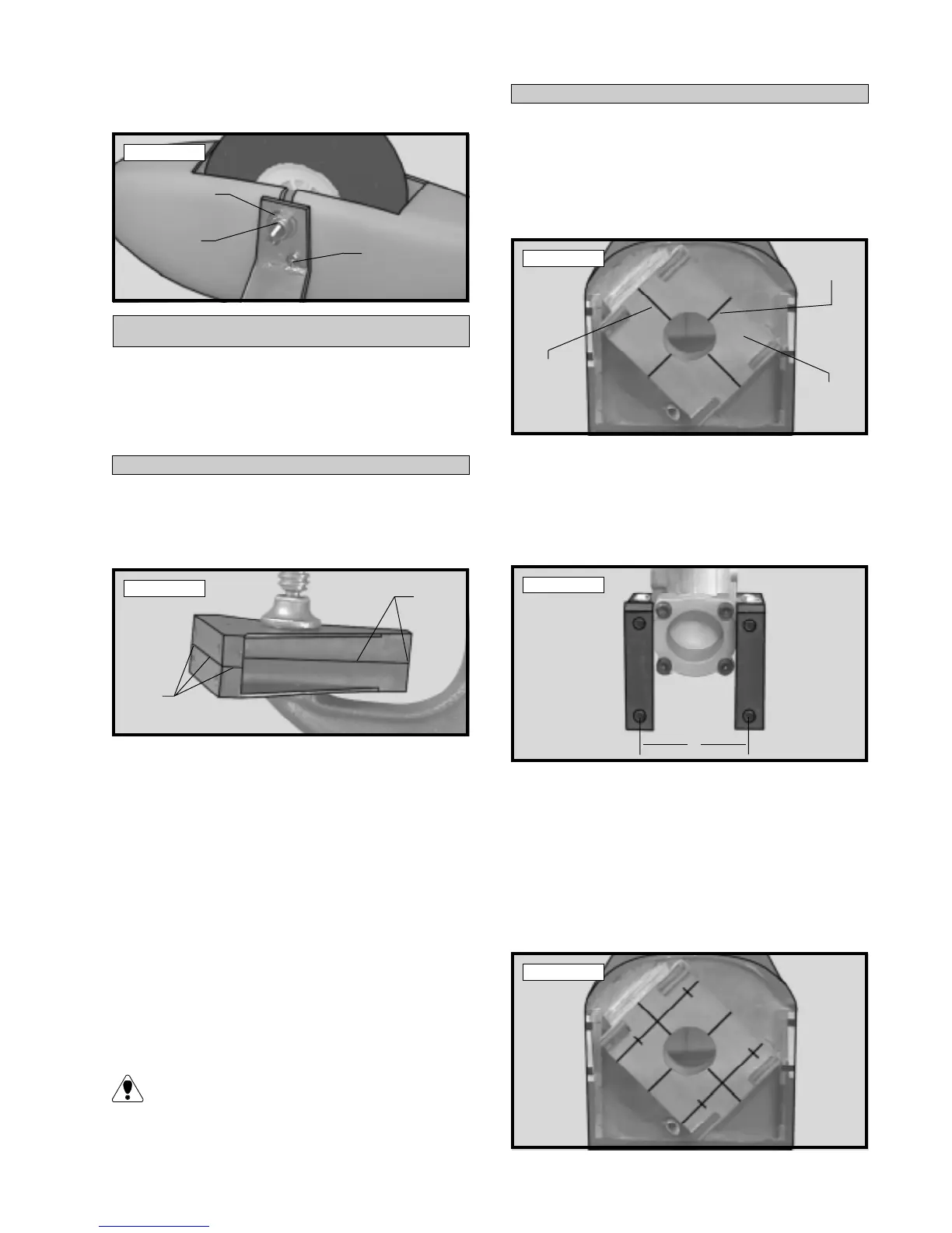
Photo # 24
ENGINE MOUNTING
Wood Screw
Nylon
Insert
Nut
Flat Washer
Align
Even
Align
Even
Vertical
Centerline
Horizontal
Centerline
Engine
Mounting
Box
D
D = Distance
Between
Predrilled Motor
Mount Holes