20
PARTS REQUIRED
q {1} Molded Fiberglass Cowling
q {2} Cowl Mounting Blocks D-30
q {3} 3mm x 6mm Wood Screws
INSTALLING THE COWL
COWL INSTALLATION
q 1) Remove the high speed needle valve and muf-
fler from the engine. Use masking tape to cover the
carburetor, muffler and glow plug openings to pre-
vent dust from getting into the engine.
q 2) Using a Dremel Tool, carefully open the three
air inlets in the front of the cowl. Trim away a small
amount at a time so you don't remove too much mate-
rial. See photo # 40 below.
Photo # 40
q 3) Using a ruler and a pen, measure back from
the front of the firewall, at the top of the fuselage,
1-3/4” and place a mark.
Do not measure from the front of the engine
mounting box.
q 4) Using a ruler and a pen, measure back 1-1/4”
from the front of the firewall, on the bottom of the
fuselage, and place two marks, to locate the two cowl
mounting blocks D-30.
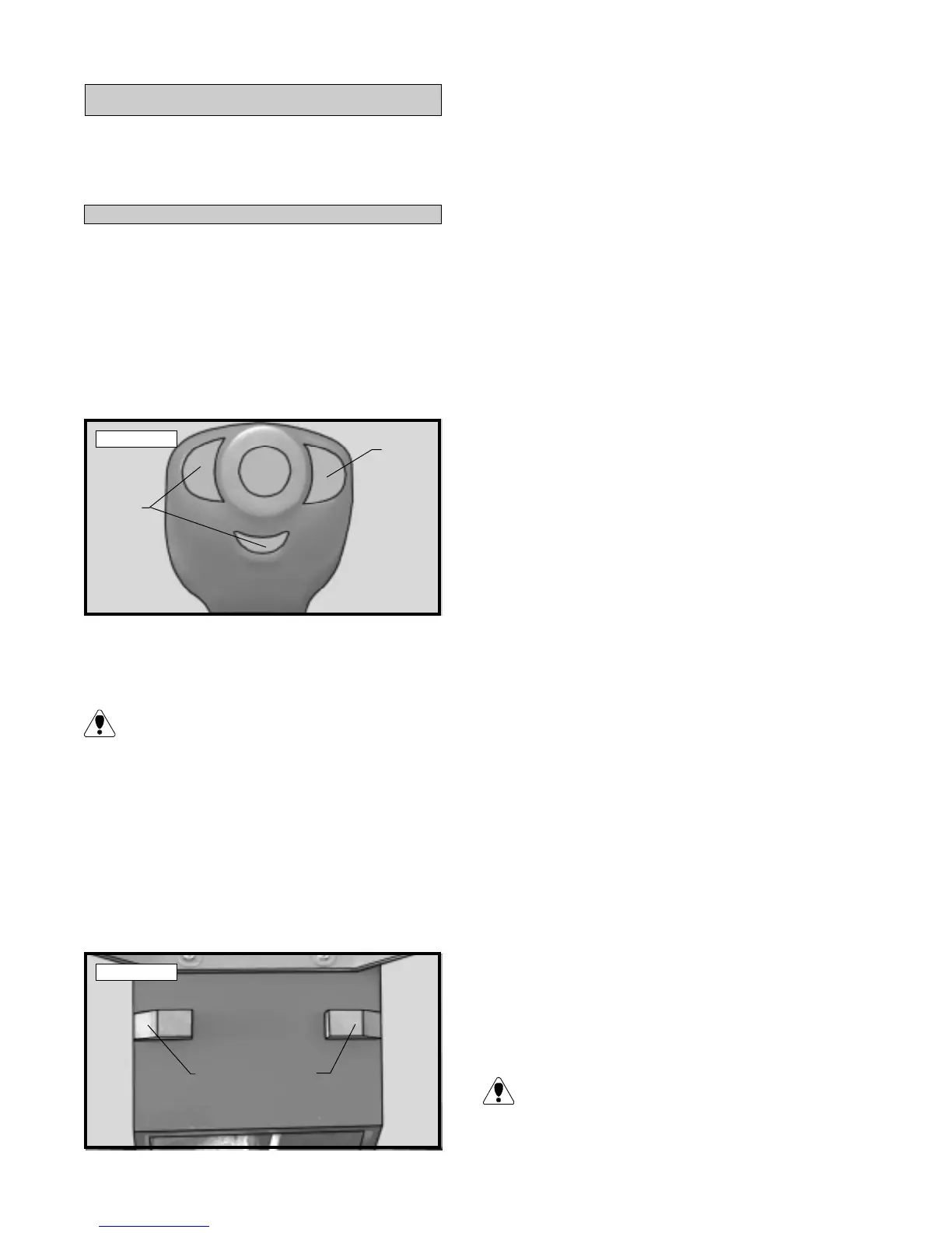
q 5) Set the blocks in place. The angle on the end
of each block should be flush with the side of the
fuselage. The front edge of the blocks should be even
with the marks you made. See photo # 41 below.
Photo # 41
q 6) While holding the blocks firmly in position,
use a pen and trace around each block . Remove the
blocks and use a modeling knife to remove the cover-
ing from just inside the lines.
q 7) Using Kwik Bond Thick C/A, glue the blocks
in position. Allow the glue to cure completely.
q 8) Slide the cowl onto the fuselage. The rear
edge of the cowl should line up flush with the mark
you made previously on top of the fuselage. You
will need to remove a portion of the cowl for engine
head clearance. Use a Dremel Tool with a sanding
drum for this purpose. Work carefully, removing a
small amount of material at time. Double check your
work frequently so you don't remove too much ma-
terial.
q 9) With the cowl on the fuselage, install the spin-
ner backplate and secure it in place. Center the cowl
at the rear. The sides of the cowl, at the rear, should
be equal distance away from the sides of the fuse-
lage. When you are satisfied that the rear of the cowl
is centered, apply a couple of pieces of masking tape
to hold it in position.
q 10) With the rear of the cowl held firmly in po-
sition, align the front of the cowl with the backplate.
The radius on the front of the cowl should be even
with the radius of the backplate. There should also
be about a 1/16” gap between the front of the cowl
and the backplate.
q 11) The cowl is held in place using three 3mm x
6mm wood screws. One screw is threaded into the
firewall at the top center of the cowl and one screw is
threaded into each of the two blocks at the bottom
sides of the cowl.
q 12) Using a pencil, mark the locations of the
three mounting screw positions on the cowl. While
holding the cowl firmly in position, drill 1/16” pilot
holes through the cowl and into the firewall and
mounting blocks.
q 13) Remove the spinner backplate and cowl.
Using a 1/8” drill bit, open the holes in the cowl only.
Opening the holes will allow the screws to pass
through without cracking or splitting the cowl.
Remove
Remove
Mounting Blocks D-30