15
q 9) Slide the fuel tank into the fuel tank com-
partment in the front of the airplane. The top of the
tank should face the top of the fuselage and rest just
up against it and the stopper assembly should engage
the predrilled hole in the firewall. The tank should
be pushed as far forward as possible. This will pre-
vent the wing from interfering with the back of the
tank when the wing is mounted.
q 10) Secure the fuel tank in place using several
pieces of foam rubber. Seal the gaps between the
stopper asssembly and the firewall using silicon
sealer. Be careful not to get any silicon sealer inside
the aluminum tubes.
FUEL TANK INSTALLATION
PARTS REQUIRED
q {1} 4mm x 200mm Nylon Pushrod
q {1} 1.5mm x 52mm Threaded Wire w/Z-Bend
THROTTLE LINKAGE
INSTALLING THE THROTTLE LINKAGE
q 1) Thread the 1.5mm x 52mm threaded wire into
one end of the 4mm x 200mm nylon pushrod. Thread
the wire about 5/16” into the pushrod.
q 2) Using a modeling knife, cut off the excess
throttle pushrod housing inside the fuselage. Leave
about 1/4” extending beyond the front bulkhead.
q 3) Slide the plain end of the nylon pushrod
wire through the preinstalled pushrod housing in
the firewall. Remove the throttle arm from the car-
buretor and attach the Z-bend in the wire to the outer
hole in the arm.
q 4) Reattach the throttle arm to the carburetor and
use a pair of pliers to make small bends in the wire, if
necessary, so the pushrod does not bind when the car-
buretor is moved from the idle to the full throttle po-
sition. See photo # 28 below.
Photo # 28
PARTS REQUIRED
q {1} Fuselage Servo Tray D-15
q {3} Aileron Servo Mounting Plates W-24
SERVO INSTALLATION
INSTALLING THE FUSELAGE SERVO TRAY
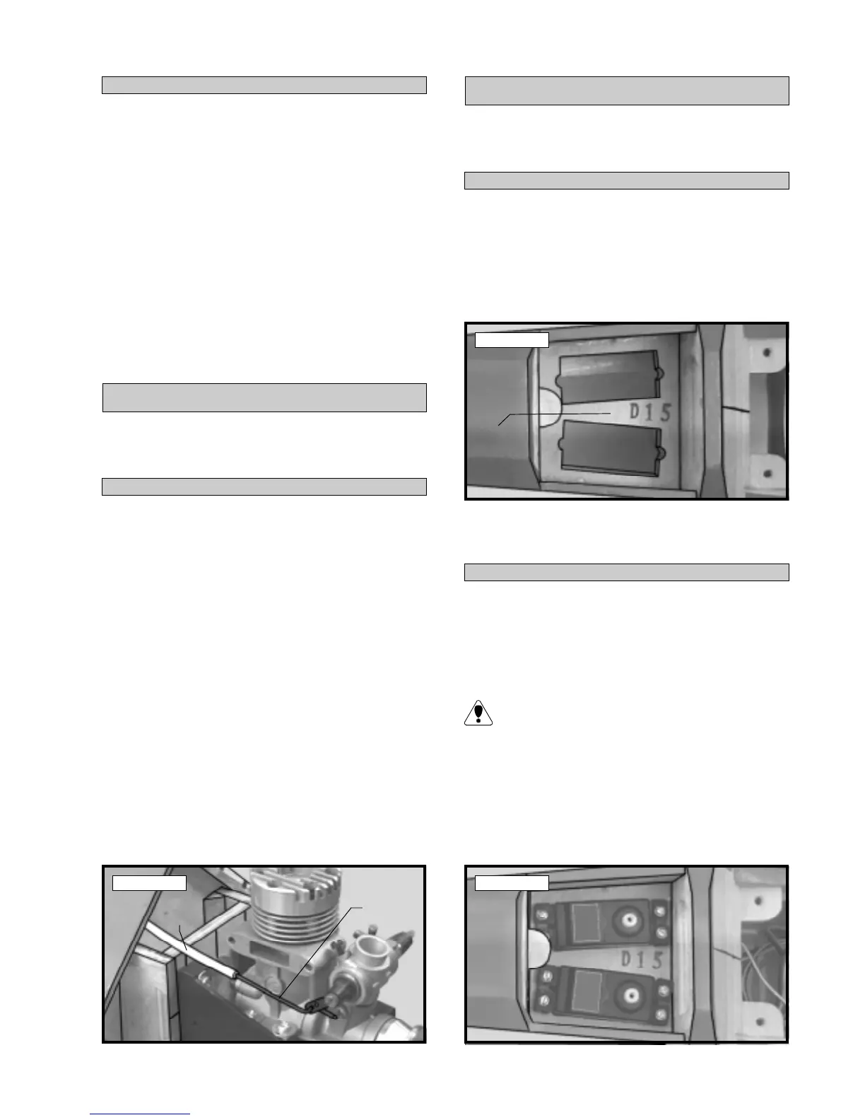
Photo # 29
q 2) When satisfied with the fit, remove the tray
and mix up a generous amount of Kwik Bond 5 Minute
Epoxy and glue the tray in place.
q 1) Remove the precovered hatch from the bot-
tom of the fuselage, just behind the wing saddle. Trial
fit the servo tray D-15 in position inside the fuselage.
The tray should rest on top of the preinstalled balsa
stringers glued to the fuselage sides. The front edge
of the tray should be pushed firmly against the rear
bulkhead. See photo # 29 below.
q 3) Install the rubber grommets and brass collets
provided with your radio system onto four servos. Test
fit two of the servos into the two precut servo holes in
the fuselage servo tray D-15. These will be the el-
evator and rudder servos.
Because the size of servos differ, you may need
to adjust the size of the precut openings.
q 4) Install the elevator and rudder servos using
the wood screws provided with your radio system.
Drill 1/16” pilot holes through the tray before install-
ing the screws. This will help prevent the wood from
splitting. Install the servos with the output shafts fac-
ing the front of the airplane. See photo # 30 below.
INSTALLING THE FUSELAGE SERVOS
Photo # 30
Nylon
Pushrod
Pushrod
Wire
Servo
Tray