14
q 9) Hold the motor mount assembly up to the
firewall and double check that the four intersecting
lines line up with the four predrilled holes in the
motor mount.
q 10) Using a 1/8” drill bit, drill the four mounting
holes through the firewall for the motor mount.
q 11) Mount the motor mount assembly to the fire-
wall using the four 3mm x 20mm machine screws,
eight 3mm flat washers and four 3mm nylon insert
nuts. Tighten the screws and nuts completely. See
photo # 25 below.
MOUNTING THE ENGINE TO FIREWALL
Photo # 25
PARTS REQUIRED
q {1} 190cc Molded Plastic Fuel Tank
q {1} Rubber Stopper
q {1} 70mm Silicon Fuel Line
q {1} Weighted Clunk
q {1} 70mm Aluminum Tube
q {1} 40mm Aluminum Tube
q {1} 30mm Aluminum Tube
q {1} 15mm Diameter Rear Squash Plate
q {1} 20mm Diameter Front Squash Plate
q {1} 3mm x 20mm Machine Screw
FUEL TANK
ASSEMBLE THE FUEL TANK
q 1) The fuel tank assembly incudes 3 different
length aluminum tubes. Discard the shortest of the
three tubes. It will not be used.
The 40mm length tube is used for the fuel
line pickup and the 70mm tube is used for
the vent/pressure line.
q 2) Using 220 grit sandpaper carefully smooth
each end of the two tubes. This will prevent the fuel
line from being cut.
q 3) Push the two aluminum tubes through the rub-
ber stopper until 1/2” protrudes from the front of the
stopper. Slide the 20mm diameter front squash plate
over the tubes at the front of the stopper and slide the
15mm diameter rear squash plate over the tubes at
the rear of the stopper. Insert the 3mm x 20mm ma-
chine screw into the center hole in the front squash
plate, then screw it through the stopper and into the
rear squash plate. Do not completely tighten the screw
at this time.
q 4) Carefully bend the longer of the two tubes
up at a 45º angle. This tube is the vent tube. When
the stopper assembly is installed in the tank, the top
of the vent tube should rest just below the top surface
of the tank. It should not touch the top of the tank.
q 5) Slide the silicon fuel tubing, with the
weighted pickup attached to one end, onto the fuel
pickup tube. See photo # 26 below.
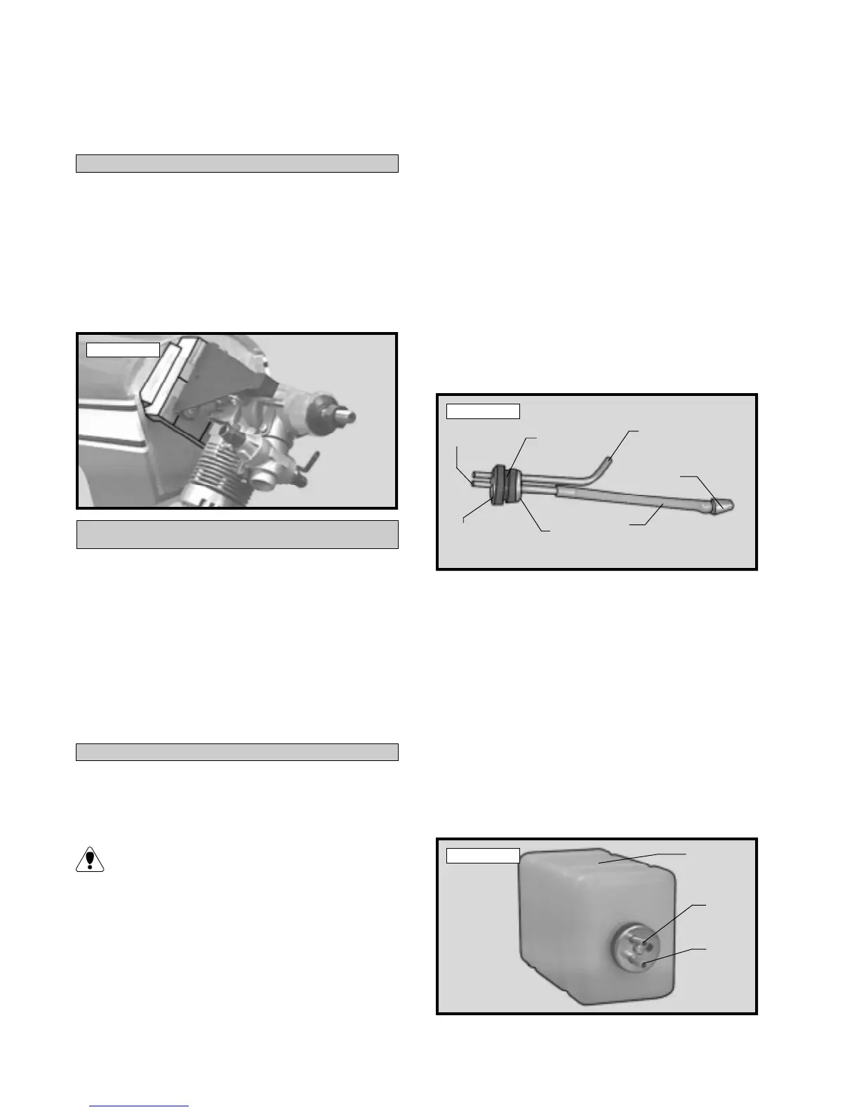
Photo # 26
q 6) Test fit the stopper assembly into the tank. It
may be necessary to remove some of the flashing
around the tank opening using a modeling knife. If
flashing is present, make sure none falls into the tank.
q 7) With the stopper assembly in place, the
weighted pickup should rest about 3/8” away from
the rear of the tank and move freely inside the tank.
q 8) When satisfied with the alignment of the stop-
per assembly tighten the 3mm x 20mm machine screw
until the rubber stopper expands and seals the tank
opening. Do not overtighten the assembly as this
could cause the tank to split. See photo # 27 below.
Photo # 27
Vent Tube
Weighted
Pickup
Fuel
Tubing
Rear
Squash
Plate
Rubber
Stopper
Front
Squash
Plate
Fuel Pickup
Tube
Vent
Tube
Fuel
Pickup
Tube
Top of
Tank