19
q 10) Thread the wire into the pushrod. You can
thread the wire in further, or back it out, until the servo
arm aligns with the output shaft of the servo.
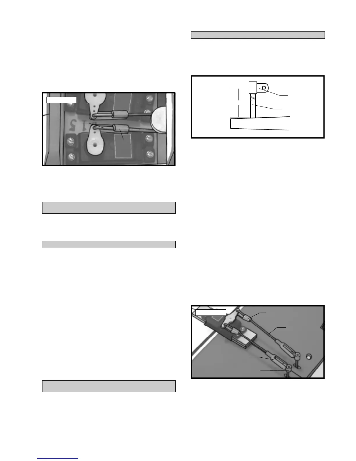
q 11) With the elevator and elevator servo in neu-
tral, install the servo arm onto the servo. The arm should
be positioned perpendicular to the servo and face the
middle of the fuselage. See photo # 38 below.
Photo # 39
q 12) Move the servo arm back and forth to test
for free movement. The pushrod should not bind in
any way. When satisfied with the movement, install
the servo arm retaining screw.
PARTS REQUIRED
q {1} Servo Hatch
q {1} 3mm x 15mm Wood Screw
INSTALLING THE SERVO HATCH
SERVO HATCH
q 1) Set the servo hatch in place on the bottom of
the fuselage. The preinstalled dowel should fully
engage the predrilled hole in the rear bulkhead.
q 2) Using a ruler and a pen locate and mark the
location of the hatch hold down screw. The hole
should be located directly in the centerline of the
hatch, 5/16” forward of the rear edge of the hatch.
q 3) With the hatch held firmly in place, drill a
5/64” pilot hole through the hatch and down through
the plywood hold down block in the fuselage.
q 4) Remove the hatch. Using a 1/8” drill bit, drill
out the pilot hole through the hatch only. Reinstall
the hatch and secure it in place using the 3mm x 15mm
wood screw. Do not overtighten the screw.
PARTS REQUIRED
q {2} Nylon Adjustable Control Horns
q {2} 2mm x 70mm Threaded Wire w/90º Bend
q {2} Nylon Clevis w/2mm I.D. Hole
q {2} Nylon Snap Keepers
INSTALLING THE AILERON LINKAGE
AILERON LINKAGE
q 1) Thread one nylon adjustable control horn
onto each aileron torque rod. Thread them on until
they are 5/8” above the top surface of the wing. See
figure # 8 below.
Figure # 8
q 2) Thread one nylon clevis at least 5/16” onto
each of the two 2mm x 70mm threaded rods with 90º
bends.
q 3) With the aileron servo centered, install one
dual-arm servo arm onto the servo. The arm should
be installed so it is parallel with the trailing edge of
the wing.
q 4) Use a couple of pieces of masking tape, taped
between the ailerons and the trailing edge of the wing,
to hold the two ailerons in neutral.
q 5) Snap the clevises onto the adjustable control
horns. With the servo arm and ailerons centered, push
the 90º bends down through the third hole out in each
side of the servo arm. Adjust the length of the wires
by turning the nylon clevises in or out until the cor-
rect length is achieved. Hold the wires in place using
two nylon snap keepers. See photo # 39 below.
Photo # 38
q 6) Move the servo arm back and forth to check
for free movement. The linkage should not bind in
any way. When satisfied with the movement, install
the servo arm retaining screw.
Snap
Keeper
Pushrod
Wire
Control Horn
Torque Rod
5/8”
Pushrod
Wire
Control
Horn
Clevis
Snap
Keeper