17
hole in the servo arm. You may need to make a slight
bend in the pushrod wire to allow it to align level
with the servo arm. See photo # 34 below.
Photo # 34
q 5) Test the movement of the throttle pushrod.
Full forward stick and full forward trim should result
in the carburetor barrel opening completely. Full back
stick and full forward trim should result in the ap-
proximate idle setting. Full back stick and full down
trim should result in the carburetor barrel closing fully.
q 6) When you are satisfied with the movement
of the pushrod, install the servo arm retaining screw.
PARTS REQUIRED
q {1} 4mm x 300mm Nylon Pushrod
q {1} 2mm x 62mm Threaded Wire w/90º Bend
q {1} 2mm x 100mm Threaded Straight Wire
q {1} Nylon Clevis w/2mm I.D. Hole
q {1} Nylon Snap Keeper
q {1} Nylon Control Horn w/Backplate
q {2} 2mm x 15mm Machine Screws
INSTALLING THE RUDDER CONTROL HORN
q 1) The centerline of the rudder control horn is
located on the left side of the rudder (looking from
behind) 9/16” up from the bottom of the rudder. Po-
sition the control horn so the clevis attachment holes
are directly in-line with the hinge line. The control
horn should also be parallel with the hinge line. See
figure # 6 below.
q 3) Mount the control horn to the rudder by in-
serting the 2mm x 15mm machine screws through the
control horn mounting base, through the rudder, and
into the backplate. Tighten the screws, but do not
overtighten them. You do not want to crush the wood.
INSTALLING THE RUDDER PUSHROD
q 4) Using a modeling knife, cut the 300mm ny-
lon pushrod to a length of 9-1/4”. Thread the 2mm x
100mm threaded wire into one end of the nylon push-
rod. For safety, thread the wire in no less than 5/16”.
q 5) Thread one nylon clevis onto the opposite end
of the 2mm x 100mm threaded wire. It should be
threaded no less than 5/16” onto the wire also.
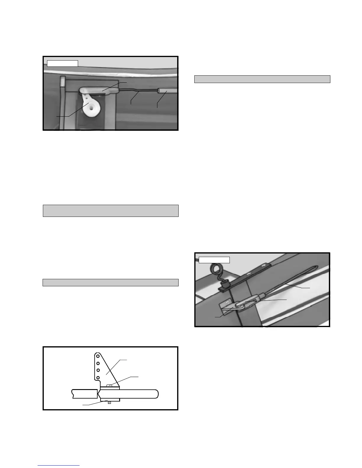
q 6) Using a modeling knife remove the covering
from over the rudder pushrod exit slot. Looking from
the back of the airplane, the slot is located on the left
side of the fuselage, 3-1/8” forward of the rudder hinge
line and 1-1/4” below the horizontal stabilizer.
q 7) Insert the plain end of the nylon pushrod into
the pushrod housing from the back. Snap the clevis
onto the rudder control horn. Move the rudder back
and forth to ensure there is no binding. See photo #
35 below.
Photo # 35
q 8) Use a couple of pieces of masking tape to
hold the rudder in neutral.
q 9) Locate a servo arm, and using wire cutters,
remove all but one of the arms. Install the 90º bend
in the 2mm x 62mm wire into the third hole out from
center. Remove the excess servo arm using wire cut-
ters. Secure the wire in place using one nylon snap
keeper.
q 10) Thread the wire into the pushrod. You can
thread the wire in further, or back it out, until the servo
arm aligns with the output shaft of the servo.
RUDDER PUSHROD
Figure # 6
q 2) When satisfied with the alignment, use a
5/64” drill bit, and the control horn as a guide, and
drill the two mounting holes through the rudder.
Nylon
Pushrod
Pushrod
Wire
Nylon
Clevis
Servo
Arm
Clevis
Control
Horn
Pushrod
Wire
Control Horn
Backplate
Screw