22
q 6) After the filler has dried, sand it smooth and
repeat as necessary until any gaps are completely
filled. Paint the pilot head, pilot bust and cockpit to
suit your tastes.
q 7) Roughen the bottom of the pilot head and the
top of the bust using 220 grit sandpaper. Using Kwik
Bond 5 Minute Epoxy, glue the pilot head to the bust.
Allow the epoxy to fully cure. See photo # 45 below.
PILOT INSTALLATION
Photo # 45
PARTS REQUIRED
q {1} Molded Clear Canopy
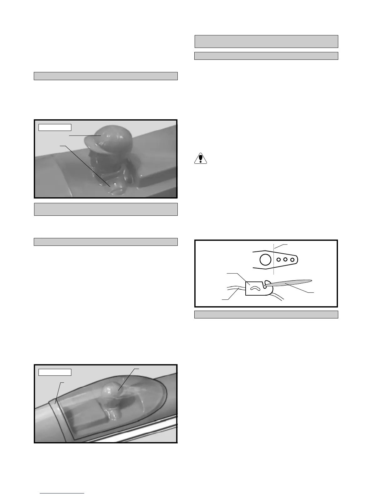
INSTALLING THE CANOPY
CANOPY
q 1) Using a modeling knife or Lexan Canopy
Scissors, cut out the canopy along the molded scribe
lines.
q 2) Trial fit the canopy. The canopy edges fit
flush with the molded recess in the cockpit deck.
Make any adjustments necessary to achieve a good
fit using 220 grit sandpaper with a sanding block.
q 3) When satisfied with the fit, glue the canopy
in place using RC256 Canopy Glue. Hold the canopy
securely in place using masking tape until the adhe-
sive completely cures. See photo # 46 below.
Photo # 46
FINAL ASSEMBLY
INSTALLING THE RECEIVER AND BATTERY
q 1) Plug the four servo leads and the switch lead
into the receiver. Plug the battery pack lead into the
switch also.
q 2) Wrap the receiver and battery pack in foam
rubber to protect them from vibration. Position the
battery pack in the fuel tank compartment and the re-
ceiver between the fuel tank and the throttle servo.
Use extra foam pieces to hold them in position.
When balancing the airplane you may need to
move the battery or receiver forward or aft to
achieve proper balance. In our test airplane, using a
Magnum XL .25 two stroke engine, the battery and
receiver were mounted as per step # 2.
q 3) Using a 1/16” drill bit, drill a hole through the
side of the fuselage for the antenna to exit. Route the
antenna out of the fuselage and secure it to the vertical
stabilizer using a rubber band. See figure # 9 below.
Figure # 9
q 4) The switch should be mounted on the fuse-
lage side at the middle of the servo compartment. Use
the faceplate of the switch itself to locate and mark
the switch cutout and mounting holes.
q 5) Cut out the switch hole using a modeling
knife. Use a 5/64” drill bit and drill out the two mount-
ing holes.
q 6) Secure the switch in place using the two ma-
chine screws provided with the radio system.
q 7) Mount the optional Cirrus On-Board Battery
Indicator and the optional Ernst charge jack to the
fuselage side. Plug the battery indicator into an empty
slot in the receiver.
INSTALLING THE SWITCH
Pilot Head
Pilot
Bust
Canopy
Cockpit
Deck
Antenna
Rubber
Band
Modified
Servo Arm
Cut
To Vertical
Fin