18
q 11) With the rudder and rudder servo in neutral,
install the servo arm onto the servo. The arm should
be positioned perpendicular to the servo and face the
middle of the fuselage. See photo # 36 below.
Photo # 36
q 12) Move the servo arm back and forth to test
for free movement. The pushrod should not bind in
any way. When satisfied with the movement, install
the servo arm retaining screw.
PARTS REQUIRED
q {1} 4mm x 300mm Nylon Pushrod
q {1} 2mm x 62mm Threaded Wire w/90º Bend
q {1} 2mm x 93mm Prebent Threaded Wire
q {1} Nylon Clevis w/2mm I.D. Hole
q {1} Nylon Snap Keeper
q {1} Nylon Control Horn w/Backplate
q {2} 2mm x 15mm Machine Screws
INSTALLING THE ELEVATOR CONTROL HORN
q 1) The centerline of the elevator control horn is
located on the bottom right side of the elevator (look-
ing from behind) 7/8” out from the fuselage side, at
the elevator hinge line. Position the control horn so
the clevis attachment holes are directly in-line with
the hinge line. The control horn should also be paral-
lel with the hinge line. See figure # 7 below.
ELEVATOR PUSHROD
Figure # 7
q 2) When satisfied with the alignment, use a
5/64” drill bit, and the control horn as a guide, and
drill the two mounting holes through the elevator.
q 3) Mount the control horn to the elevator by in-
serting the 2mm x 15mm machine screws through the
control horn mounting base, through the elevator and
into the backplate. Tighten the screws, but do not
overtighten them. You do not want to crush the wood.
INSTALLING THE ELEVATOR PUSHROD
q 4) Using a modeling knife, cut the 300mm ny-
lon pushrod to a length of 8-3/4”. Thread the 2mm x
93mm prebent threaded wire into one end of the ny-
lon pushrod. Thread the wire in no less than 1/2”.
If you look closely at the prebent threaded wire
you will notice that before and after the bend
one side of the wire is longer than the other. The
longer side should thread into the nylon pushrod.
q 5) Thread one nylon clevis onto the opposite end
of the 2mm x 93mm prebent threaded wire. It should
be threaded no less than 5/16” onto the wire.
q 6) Using a modeling knife remove the cover-
ing from over the elevator pushrod exit slot. Look-
ing from the back of the airplane, the slot is located
on the right side of the fuselage, 3-1/8” forward of
the rudder hinge line and 9/16” below the horizon-
tal stabilizer.
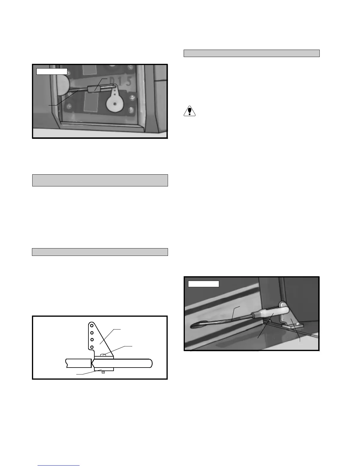
q 7) Insert the plain end of the nylon pushrod into
the pushrod housing from the back. Snap the clevis
onto the elevator control horn. Move the elevator
up and down to ensure there is no binding. See photo
# 37 below.
Photo # 37
q 8) Use a couple of pieces of masking tape to
hold the elevator in neutral.
q 9) Locate a servo arm, and using wire cutters,
remove all but one of the arms. Install the 90º bend
in the 2mm x 62mm wire into the second hole out
from center. Remove the excess portion of the arm
using wire cutters. Secure the wire in place using
one nylon snap keeper.
Snap Keeper
Pushrod
Wire
Control Horn
Backplate
Screw
Clevis
Control Horn
Pushrod
Wire