22 MCP15-500.7
Error Codes” section in the next column to clear the errors.
10. For furnace models with Digit 11=6 or 8, verify the furnace
control board and modulating valve is communicating
properly by adjusting the Fire Rate Input on the control
board from 10.0 to 2.0 with the up and down buttons.
• Thehighfiremanifoldpressuremaybeintherangeof
3.3" W.C to 3.5" W.C. at the 10.0 Fire Rate Input setting.
• Thelowfiremanifoldpressuremustnotgobelow
0.2" W.C. at the 2.0 Fire Rate Input setting. If the manifold
pressure drops below 0.2”W.C. or flame is lost, repeat
the "Check/Adjust Pressure at Combination Gas Valve"
section on the previous page and then repeat the “Low
Fire Setting” sequence described above.
11. Once the setting of the modulating valve has been
completed, replace the valve cover that was removed
earlier.
12. Move the field installed manual shut-off valve to the “OFF”
position, remove the manometer, and replace the 1/8" pipe
plug.
13. After the plug is in place, move the field installed manual
shut-off valve to the “ON” position and recheck the pipe
plug for gas leaks with soap solution.
14. For units with furnace model Digit 11=4, repeat the entire
process for the 2nd furnace.
Placing Furnace Control Into “Checkout Test Mode”
(Applies to furnace models with Digit 11=6 or 8)
The furnace control board (Figure 23.1) has functionality to be
put it in a manual operation “Checkout Test Mode” for testing
purposes as noted in the previous sections for checking and
setting gas pressure. To enter that mode, perform the following
steps:
1. The Checkout Test mode is only available when the furnace
control board detects an “E09” error condition (No Firing
Rate Input). To accomplish this, temporarily disconnect wire
#804 from the furnace control board and create a call for
heat from the main Carel controller. Be sure to insulate the
end of the signal wire so it cannot cause a short.
2. Press the MODE button for at least 4 seconds until the LED
display changes to display “Lo9”.
3. Press the DOWN button briefly to change the display to
“tSt”, and then briefly press the MODE button to enter the
Checkout Test mode.
4. When the Checkout Test mode is entered, the control board
will initiate a normal ignition sequence with the Firing Rate
Input set to a simulated 10.0 VDC. The simulated Firing
Rate Input can be set to different 1.0 VDC step values from
10V to 2V. A 10V signal will give maximum fire rate while
a 2V signal will give the minimum fire rate. Once burner
ignition has been achieved and the control enters the RUN
mode, the normal runtime data parameters, including the
Firing Rate, will be continuously displayed on the furnace
control board LED indicators.
5. If a lockout error condition occurs, or the MODE button is
depressed for more than 4 seconds, or there is no push
button activity for 30 minutes, then the Checkout Test mode
will be exited.
Clearing Furnace Control Board Error Codes
1. Fault codes can be reviewed by pressing the MODE button
for at least 4 seconds until the LED display changes to
display “Lo9”. Refer to Figure 23.1 for location of buttons
and LED display.
2. Briefly press the MODE button again to review the fault
codes. Up to 15 fault codes are stored and can be reviewed
START-UP PROCEDURE - CONTINUED
8. Adjust the Low Fire Setting as follows:
a. For units with furnace model Digit 11=6 or 8, place
the furnace control into the “Checkout Test Mode” as
instructed in the next section and set the Fire Rate Input
to 2.0.
b. Press and hold Button #2 on the modulating valve until
the LED light blinks red, then release.
c. With the valve now in the low fire setting mode, confirm
or adjust the low fire manifold pressure to be no less than
the minimum shown on the furnace serial plate in the box
called “Min. Manifold Pressure”. If the pressure needs to
be adjusted:
Press or hold Button #1 to increase gas flow and press
Button #2 to decrease gas flow. It is best to push
and release button #2 to single step the valve to the
minimum manifold pressure. Pressing and holding the
button is likely to cause the valve to close too far and
lose flame.
d. Save the setting by simultaneously holding Buttons #1
and #2 until the LED turns OFF. If this is not performed
within 5 minutes, the control will default to the previously
saved settings and return to normal operating mode.
9. For furnace models with Digit 11=6 or 8, if no errors or
alerts were recorded by the board (these will be on the
3 LED displays as an “A” or “E” followed by a number),
proceed to the next step. If any alerts or errors were logged
by the board, refer to the “Clearing Furnace Control Board
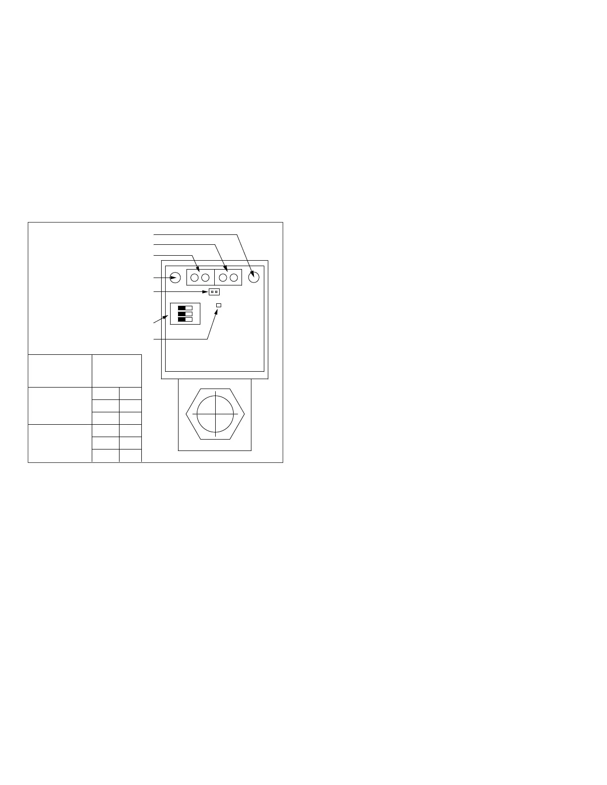
Figure 22.1 - Maxitrol Modulating Valve Adjustments
ON
1 2 3
1 2
3 4
BUTTON #1
BUTTON #2
CONTROL SIGNAL
WIRING TERMINALS
SUPPLY POWER
WIRING TERMINALS
POSITION FEEDBACK
WIRING TERMINALS
(ONLY ON UNITS WITH FURNACE
MODEL DIGIT 10=6, 7, OR 8)
DIP SWITCHES
(SEE TABLE FOR SETTINGS)
LED INDICATOR
Furnace Model
Digit 11
(Capacity Control)
DIP Switch
Settings
4
SW #1 OFF
SW #2 OFF
SW #3 OFF
6 or 8
SW #1 OFF
SW #2 ON
SW #3 OFF
or adjust the high fire manifold pressure to be 3.5" W.C.
If the pressure needs to be adjusted, press or hold
Button #1 to increase gas flow and press or hold Button
#2 to decrease gas flow.
e. If 3.5" W.C. cannot be attained, recheck the inlet gas
pressure as described previously. After addressing any
issues, if 3.5" W.C. still cannot be attained, step the
valve closed using button #2 to the point where manifold
pressure begins to be impacted. If the pressure at that
point is less than 3.3" W.C., corrective action is required.
f. Save the setting by simultaneously holding Buttons #1
and #2 until the LED turns OFF. If this is not performed
within 5 minutes, the control will default to the previously
saved settings and return to normal operating mode.