23MCP15-500.7
START-UP PROCEDURE - CONTINUED
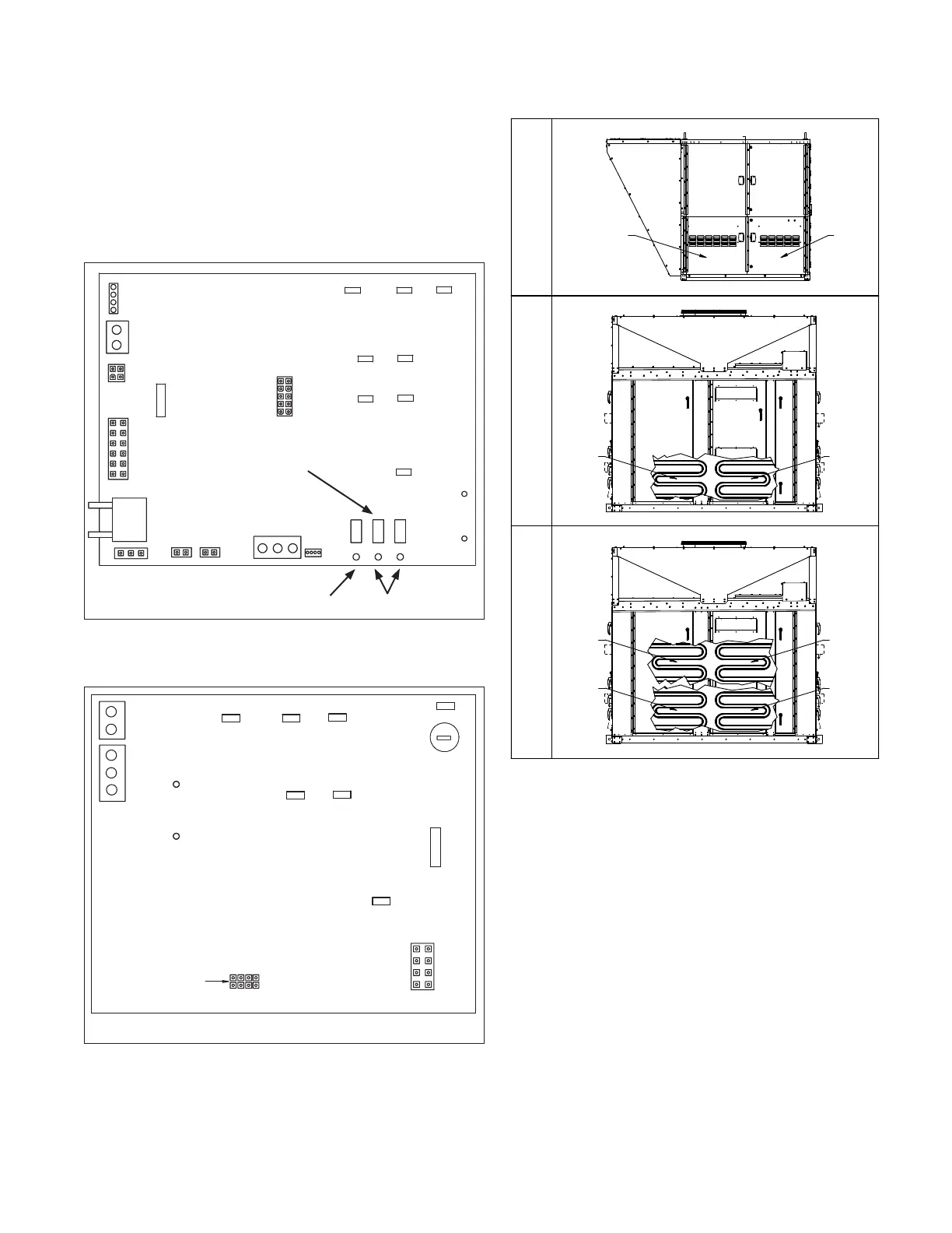
Figure 23.1 - Furnace Master Control Board
(Furnace models with Digit 11=6 or 8 only)
FLAME VOLT
1.0VDC=1MCIROAMP
+
_
FLAME ROD
IND-L2
IND-L1
L2
L1
FUSE
3
W
R
VB1201
CONTROL BOARD
IND-L2
IND-L1
GND
A
B
GND
ABCD
SLAVE
GND
WHITE
JUMPER SETTING MUST
MATCH FURNACE SLAV E
DESIGNATION. 1
Figure 23.2 - Furnace Slave Control Board
(Furnace models with Digit 11=8)j
NOTE: FOR ACTUAL WIRING TO THE FURNACE CONTROL BOARD, PLEASE REFER TO THE
WIRING DIAGRAM LOCATED IN THE FURNACE CONTROL COMPARTMENT.
j This applies to C- and D-Cabinet sized units with furnace model Digit 11=8.
Refer to Figure 23.3 for identifying which furnace is the Master and which
furnace(s) are the Slave(s).
J13
J8
J12
J6
J7
J4
+
_
-
+
W
R
+
_
FLAME ROD
L2
L1
ALARM
OUTPUT
FUSE
3
J13
J8
J12
J6
J7
J4
-
+
VB1200
CONTROL BOARD
DOWNUPMODE
+
_
PRESSURE
SENSOR
FLAME VOLT
1.0VDC=1MCIROAMP
+
_
ID
PLUG
AUX-L2
AUX-L1
IND-L2
IND-L1
L2
L1
GND
BA
GND
NOTE: FOR ACTUAL WIRING TO THE FURNACE CONTROL
BOARD, PLEASE REFER TO THE WIRING DIAGRAM LOCATED
IN THE FURNACE CONTROL COMPARTMENT.
MODE BUTTON
7-SEGMENT
LED DISPLAY
UP/DOWN BUTTONS
by pressing the UP or DOWN buttons. Codes will be
displayed followed by the number of days since the fault
was detected.
3. To clear the fault codes from memory, press the DOWN
button until “CLr” is displayed. Press and hold the MODE
button to clear the memory. The board will then revert to
normal operation.
D-CABINET SIZE UNIT
(OVER 800,000 BTU/HR)
D-CABINET SIZE UNIT
(UP TO 800,000 BTU/HR)
C-CABINET SIZE UNIT
(ALL GAS HEAT SIZES)
SLAVE A
SLAVE C
SLAVE B
MASTER
SLAVE A MASTER
SLAVE A MASTER
Final Check
1. Operate furnace (all furnaces for units with multiple heat
exchangers) at high fire and verify that gas pressure to the
INLET of the combination gas control valve is maintained
at 6”-7” W.C. If the pressure cannot be maintained at 6”-7”
W.C. while operating at high fire, the gas supply system is
undersized and must be corrected and the entire check and
adjustment of gas pressures section must be repeated.
2. Once all gas pressures have been checked and are at
the proper settings, shut the unit down and move the field
installed manual shut-off value to the “OFF” position.
3. Remove all testing equipment and replace any hardware
(plugs, covers, etc.). For furnace models with Digit 11=6,
replace wire #804 that was temporarily removed when the
control was placed in the “Checkout Test Mode”.
4. Close the unit access doors.
Figure 23.3 - Furnace Master/Slave Locations
k Furnace locations are shown for reference, not the location of the furnace
controls. Refer to the figures on pages 25 through 27 for controls location.