SR3 Type 1 Technical Manual TSP005.doc Issue 5.0 – Jan 2005
Money Controls 2005. All rights reserved.
Page 29 of 50
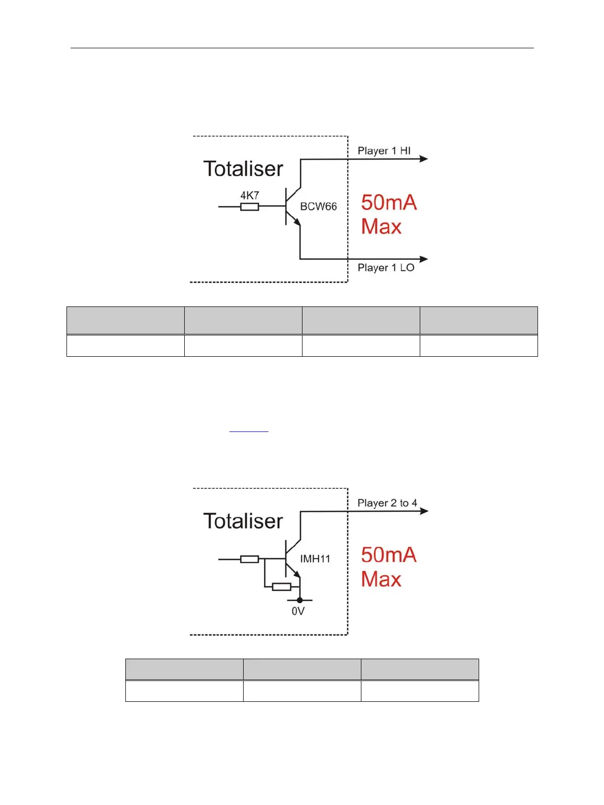
18.3 Player 1 HI / Player 1 LO
Figure 14: Player 1 HI / Player 1 LO Output
OFF State Voltage
(Player 1 HI)
ON State Voltage
(Player 1 HI)
ON State Voltage
(Player 1 LO)
Sink Current
+30V DC Max +0.5 V DC Max 0V Min 50mA Max
18.4 Player 2 to 4
Indicates a game output to the relevant player. Game pulse width is defined by
the parameters shown in Table 13.
Figure 15: Player 2 to 4 Outputs
OFF State Voltage ON State Voltage Sink Current
+30V DC Max +0.5 V DC Max 50mA Max