OPI-PulseNGKit-en-141106
Version: 2.01
Page 12 of 31
021,725,1*62/87,216
Operating Manual
PulseNG Kit
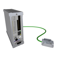
Diagnosis and LED signals
The IBU-NG provides the following LED signals to display the described statuses:
LED Color Status Meaning
SENS green continually on
blinking
Connection with PulseNG sensor OK
No connection with Pul seNG sensor
Possible causes:
Not plugged in correctly or broken cable
STAT green continually on
continually off
Device ready
Device not ready
IN1-IN5 yellow continually on Shows respective input status, depending on
whether contact is designated as normally
open (N.O.) or normally closed (N.C.).
OUT1-
OUT5
red continually on Shows respective output status, depending
on whether designated normally open (N.O.)
or normally closed (N.C.) contact.
Only OUT1 red continually on Device in boot loader mode
* Current IP address: 192�168�1�241
Table 4: Diagnosis and LED signals
Sensor Connection
A 4 pin M8 round connector with pins connects Pulse NG sensor and IBU-NG.
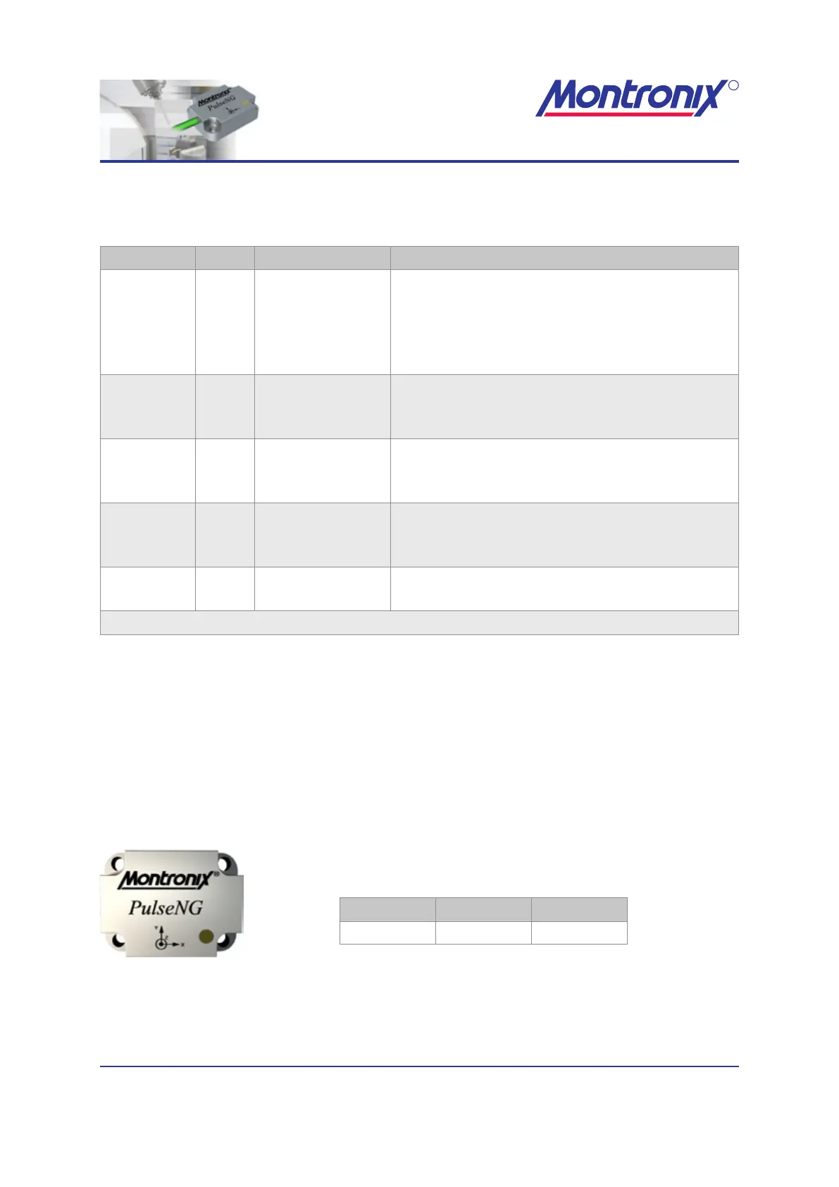
PulseNG
Dimensions
Figure 4: PulseNG
Height Width Depth
30 mm 40 mm 11 mm
Table 5: PulseNG sensor dimensions