OPI-PulseNGKit-en-141106
Version: 2.01
Page 9 of 31
021,725,1*62/87,216
Operating Manual
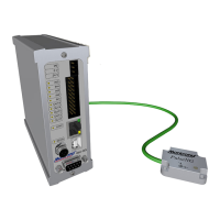
PulseNG Kit
IBU-NG
Dimensions
Height Width Depth
120 mm 42 mm 120 mm
Table 1: IBU-NG dimensions
• robust aluminum housing, with DIN rail attachment according to EN 50022
Please observe
Installation of the IBU-NG may require wiring
operations in a high-voltage area� In order to
avoid accidents due to electrical current
(serious bodily injury or even death), only
qualied professionals may perform the
installation!
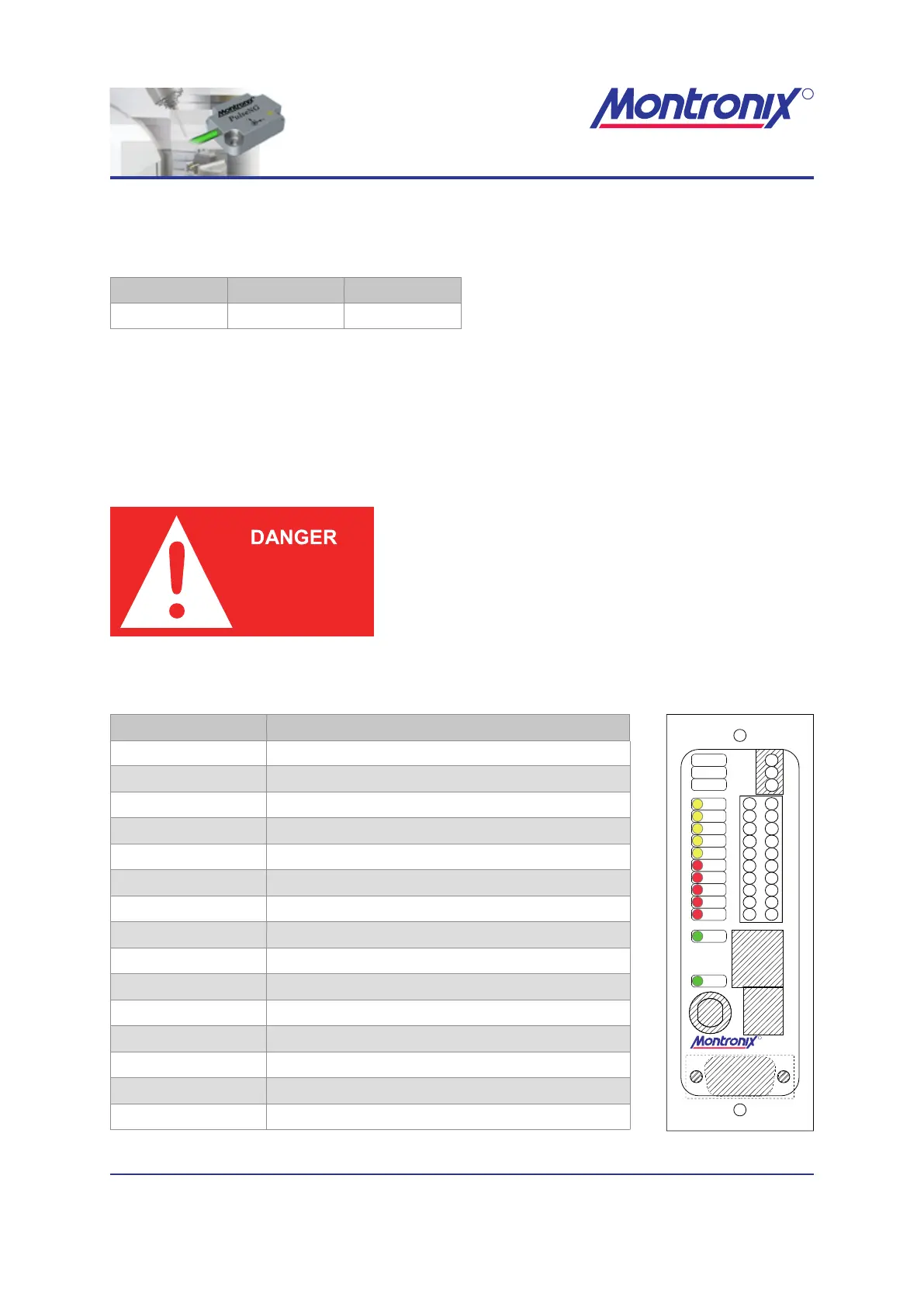
Labeling Function
PE Ground
0 V GND voltage supply
24 V +24 V voltage supply
IN5 Reset, delete errors
IN4 Monitor Active
IN3 Bit 3 (Value 4) of scenario number
IN2 Bit 2 (Value 2) of scenario number
IN1 Bit 1 (Value 1) of scenario number
OUT5 Ready
OUT4 Machine emergency stop
OUT3 Limit 3 triggered
OUT2 Limit 2 triggered
OUT1 Limit 1 triggered
STAT LED for IBU-NG status
SENS LED for sensor status
Table 2: IBU-NG labeling
Figure 1: IBU-NG front
OUT1
OUT2
OUT3
OUT4
OUT5
IN1
IN2
IN3
IN4
IN5
24 V
0 V
PE
STAT
SENS
IBU-NG
USB
LAN
2
4
6
8
10
12
14
16
18
20
1
3
5
7
9
11
13
15
17
19
24V
0V
PE
R
021,725,1*62/87,216