www.miinet.comMoore Industries-International, Inc.
- 13 -
User’s Manual
225-748-00P
August 2024
+
–
143214321432
Thermocouple
and Millivolt
Input
2-Wire RTD
or Decade
Resistance Box
143
2
3-Wire RTD
or Decade
Resistance Box
4-Wire RTD
or Decade
Resistance Box
1432
Potentiomete
Figure 2.1. Sensor Hook-Up Guide
Bench Check Procedure
1. Sensor Input:
In order to provide an input to your STA TPRG you will need to use an appropriate input
simulator. By example – if you plan to use your STA with a thermocouple input you will
need to use a thermocouple simulator to provide the appropriate input during your bench
check. The same goes for an RTD simulator, a millivolt source, a potentiometer, or a
decade resistance box. Use whichever input source is correct for your intended application.
Please see Figure 2.1 for the correct sensor input connections.
2. Power Input:
Connect the appropriate power source as shown in Figure 2.2.
Programmable RTD, T/C, Ohms, mV and Potentiometer Safety Trip Alarm
STA
TPRG
SECTION 2
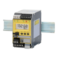
Figure 2.2. STA
(TPRG) Hook-Up Diagram
MILLIVOLT
SOURCE
OR T/C
SIMULATOR
_
+
OHMS
OR RTD
SIMULATOR
SELECT
DOWN
UP
COM
READY
INPUT TRIP 1TRIP 2
FAULT
STA
SAFETY
TRIP
ALARM
TAG
See Table 3.4
for Sensor
Hook-up Guide
AC OR DC
POWER
SUPPLY
GND-
+