www.miinet.comMoore Industries-International, Inc.
- 49 -
User’s Manual
225-748-00P
August 2024
4. STA Status– Includes Fault Alarm Status indicator, “Reset Input Fault” button and displays the
problems or faults with the instrument.:
Fault Alarm on STA not tripped (green light)
Fault Alarm on STA tripped (red light)
Note: The STA Status indicator and Status LED are updated whenever the user clicks download,
upload, or “Reset Input Fault” as well during monitoring mode.
The “Reset Input Fault” button can be used to reset the latched FAULT alarm and relay if the fault
was generated by an input diagnostic. If the input error is not cleared when resetting the fault
alarm, the error condition will immediately be re-applied and will not cause the relay to glitch.
Note: The Fault Alarm trips on internal, input and user conguration diagnostics. User
conguration faults will clear automatically once the conguration is valid. Input faults can be
cleared by pressing the “Reset Input Fault” button, or by power cycling the unit. Internal faults
require the unit to be power cycled and will not be cleared by this button. See STA Diagnostics &
Fault Alarms in Section 6 for more information.
Note: The “Reset Input Fault” is disabled when there is no unit connected.
5. Variables (PV, AO, and RJC)– Displays the selected Process Variable, Analog Output and
Reference Junction Compensation value.
6. STA Device Info– This displays instrument configuration, device identification, hardware
revision and software revision.
7. Progress Bar– This bar stays in motion any time the STA is monitoring, uploading, or
downloading.
8. Communications– Notifies user of current PC connection/communications status.
9. Input Tab– Use this tab to set your input parameters. Refer to the Input section for a
complete description.
10. Input Scaling Tab– If you choose to enable the scaling feature, the parameter would be
configured at this window and to set a Custom EGU. Refer to the Scaling section for a complete
description.
11. Display Tab– Used to set up the appearance of the STA’s LCD screen. Refer to the Display
section for a complete description.
12. Alarms Tab– Alarm parameters are configured using these windows. Refer to the Alarms
section for a complete description.
13. Analog Output Tab– Configuration of the analog output (if your instrument is equipped with
the -AO option) is performed here. Refer to the Analog Output section for a complete description.
14. Summary Tab– Displays the Data Source, Model and all Configuration parameters for
Input Type, Trimming, Scaling, Display Settings, Alarm Settings, and Analog Output Settings in a
summarized format.
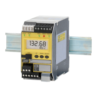
Programmable RTD, T/C, Ohms, mV and Potentiometer Safety Trip Alarm
STA
TPRG
SECTION 5