www.miinet.com Moore Industries-International, Inc.
- 58 -
User’s Manual
225-748-00P
August 2024
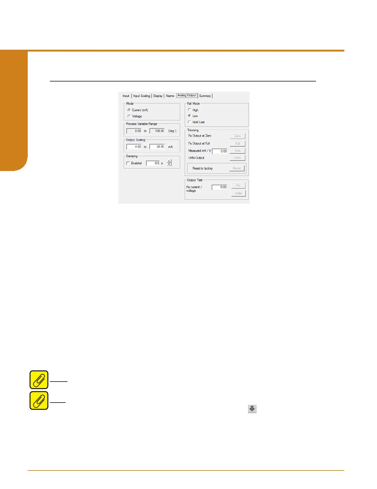
Analog Output
If your instrument is equipped with the -AO option, proceed with the following instructions:
Mode– Your desired output mode; Current or Voltage.
Process Variable Range– Displays the selected process variable range in the “Measurement
Mode” section of the Input screen.
Output Range– Sets your output limits. Set your Output Range. Enter a low and high value.
Damping– Output damping applies filtering to slow the response of the output so that momentary
input variations reduce output spikes. The time setting (0-30 seconds) defines how long it takes
for the output to reach 63% of the target value Select “Enabled” if you choose to use Damping.
Enter your damping time from 0-30 seconds in 0.5 second intervals into the “Damping” text box.
Fail Mode– In the case of an input failure, you have the ability to set a mode you choose to alert
of the failure.
High/Low– Choosing either of these options will send the output to a High (23.6mA for current;
11.0V for voltage) or Low (3.6mA for current; -0.5V for voltage) fail mode, respectively.
Hold Last– This will display the last value present before the failure.
Note: The AO must be set to fail low if used in a safety system - please refer to section 7 for more
information
Note: Once you have configured all parameters, download to the unit by selecting “Download”
in the Transfer dropdown menu located in the Status Bar. Or, click the button in the Menu
Bar.
Figure 5.5. Analog Output Tab
Programmable RTD, T/C, Ohms, mV and Potentiometer Safety Trip Alarm
STA
TPRG
SECTION 5