www.miinet.com Moore Industries-International, Inc.
- 8 -
User’s Manual
225-748-00P
August 2024
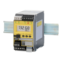
Programmable RTD, T/C, Ohms, mV and Potentiometer Safety Trip Alarm
STA
TPRG
SECTION 1
options for the STA.
Moore Industries model numbers for STA are structured as follows:
STA / TPRG / 3PRG / U / -AO [DIN]
Unit / Input / Output / Power / -Options [Housing]
Refer to Section 10 Ordering Information for a quick reference table of ordering information
INPUT
TPRG
The
STA (TPRG) supports RTD, T/C, mV, Potentiometer and Ohms as configurable inputs.
These inputs can be trimmed and scaled, refer to the STA Configuration sections of this
manual for additional information.
OUTPUT
3PRG
The STA has three programmable contact closure alarms. One relay is factory configured
as a Fault alarm and the remaining two relays are user-configurable Trip alarms. A dual
color LED (Red/Green) is provided with each alarm to indicate its condition.
The fault alarm trips on a self-diagnosed failure within the STA or on any of its inputs. This
alarm is latching and has to be reset by the user. Only user configuration faults will clear
automatically once the configuration is valid. Input faults can be configured to Latch or not
Latch and can be cleared either by the “RESET FAULT” menu or by the MR terminals if
configured to reset both latched Tripped Alarms or input faults. Self-Diagnosed unit faults
can only be cleared by power cycling the unit.
Note: For STA units with rmware versions 1.5 and earlier, the fault alarm has no conguration
options, is always latched and cannot be reset by Manual Reset (MR).
For more information refer to the Diagnostics and Fault Alarm section.
The Trip alarms are configurable for high or low trip with an adjustable dead band. These
alarms can be latching or non-latching. Latched alarms are reset through the Manual
Reset (MR) terminals.
The relay outputs have a 3A@250Vac or 3A@30Vdc, 50/60Hz non-inductive contact
rating. The contact arrangement is SPDT (1FormC). All outputs are fail safe and will de-
energize to trip (DET) with normally open (NO) and normally closed (NC) relay contacts.
Refer to the Alarm Terminology and Configuring the Alarms sections of this manual for
additional information.