#65060/INTL-K-10.2020 MORIA 13
XIII. DRAWINGS
A. CONTROL UNIT (FRONT)
Figure Description
1 Cover
2 Chamber holder
3 Pump indicator – green LED
4 Pump indicator – red LED
5 Low Vacuum LED indicator
6 Low Vacuum switch
7 Vacuum Level Indicator
8 “TEST” switch
9 Battery Level Indicators : Acceptable – green LED
10 Battery Level Indicators: Low – red LED
11 Main Power Supply Indicator – green LED
12 Manual mode indicator
13 Mode selection switch
14 Mode Display : automated
15 Mode Display and pressure display
16 Low pressure display – yellow LED
17 Correct pressure display – green LED
18 High pressure display – yellow LED
19 One Use-Plus blue connector
20 Speed 1/Speed 2 Switch (for M2, M2SU and One Use-
Plus)
21 M2 grey connector
22 Epi-K™ yellow connector
23 Turbine connector
24 Aspiration tubing connector
B. CONTROL UNIT (BACK)
Figure Description
1 Control knob to adjust gas pressure to the turbine
2 Quick Connector for Nitrogen/Air supply
3 Connector release
4 Residual Gas Drain Switch
5 MORIA reference and Serial Number
6 Volume of Epi-K™ Footpedal Steps
7 CE mark, manufacturer address
8 Footpedal Connector
9 Main OFF (0) /ON (1) Switch
10 Fuse Housing and 115V – 230V Selector
11 Main Power Supply Connector
12 Power supply informations
13 Pumps air release
14 Screws
C. FOOTPEDAL
Figure Description
1 Vacuum footpedal
2 Forward keratome pass or Turbine ON
3 Backward pass
4 IPX6 (serial number above 8000)
D. CONNECTING AND DISCONNECTING NITROGEN/
AIR HOSE (#19120)
Figure Description
1 To connect : approach the hose…
2 … then screw it
3a To disconnect : rst push the blue ring toward the
unit…
3b … then pull the hose towards the back
E. HOW TO SELECT THE OPERATING VOLTAGE (115V
OR 230V POSITION)
Figure Description
1 Switch OFF the control unit.
2 Gently open the door.
3-4 Remove the selector and select the right voltage
5 Reposition the selector and close the door
F. CHANGING THE BATTERY
Figure Description
1 Unscrew completely the 2 screws located at the back
of the control unit
2 Slide the cover towards the front
3 Lift the cover from back to front in 2 steps (1 – 2)
4 Unplug the battery
5 Unscrew the 2 screws
6 Remove the metal piece (while keeping screws in
place)
7 Lift the battery with the plastic strap
8 Replace with a new battery, reposition and screw the
metal piece, plug the new battery, replace and screw
the cover
9 Discard the battery in an appropriate collection bin.
The used battery is classied as waste, which must
be dealt with according to the specic regulations for
collection, treatment, recycling and disposal set out in
directive 2006/66/EC of 9 September 2006 relating to
batteries and accumulators and waste batteries and
accumulators. As such the battery must be disposed of
at an appropriate collection point.
G. CHANGING FUSES
Figure Description
1 Switch OFF the control unit.
2 Gently open the door with screwdriver
3 Remove the cartridge
4 Change the 2 fuses
5 Replace the 2 fuses
H. INSTALLING TUBING
Figure Description
1 Place the chamber in position
2 Get the chamber down in the chamber maintener
3 Do not reverse chamber position of the aspiration
tubing
4 If liquid appears in the chamber, replace it immediately
5 Visually check tubing integrity before and after set up
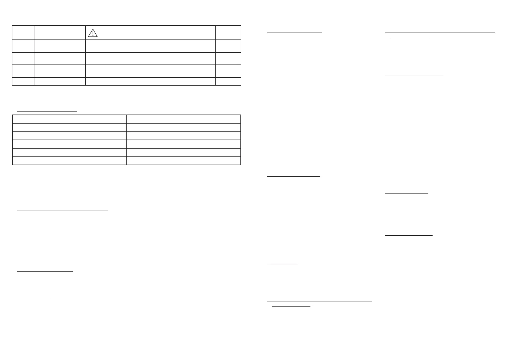
C. REPLACING FUSES
Steps What to do
IMPORTANT WARNINGS
Related
picture
1 Switch OFF the control
unit.
Before opening the control unit, switch OFF the control unit and
remove the cord.
B9
2 Gently open the door
with screwdriver
B10
G1-G2
3 Remove the cartridge
and change the 2 fuses
500 mA high switching power G3-G4-G5
4 Close the door G1
XII. WARRANTY
A. SCOPE OF WARRANTY
DESCRIPTION MORIA reference
EVOLUTION 3E Console (Except Battery) 19380
EVOLUTION 3-3E Control Footpedal 19361
EVOLUTION 3E Control Footpedal Epi-K™ 19381
EVOLUTION 3E Footswitch - China 19381C
EVOLUTION 3E footswith - Japan 19381J
• The above items as well as spare parts and labor necessary for their repair are covered by
warranty. Any items returned must be sent in their original packaging, after having previously been
decontaminated.
• The maintenance operations and the replacement of spare parts will be exclusively carried out by
technicians authorized by MORIA.
B. NON-APPLICATION OF WARRANTY
The warranty will not be applicable under any of the following conditions:
• Defects or malfunction that occur out of the warranty period (paragraph XII.C.).
• Normal wear and tear.
• Negligence or usage that does not comply with the specications in the user manual.
• The use of supplies, spare parts, or accessories other than those supplied by MORIA (for example:
blades and tubing not supplied by MORIA).
• Disassembly, modication, or intervention carried out on the devices by a person not authorized
by MORIA.
C. WARRANTY PERIOD
• The warranty takes effect on the date the material is dispatched.
• The duration of the warranty is 12 months from the date of effect.
D. LIABILITY
• The liability of MORIA is limited to the supply of the services mentioned in paragraph XII.A. MORIA
will not be held responsible for any direct or indirect damage notably nancial, suffered by the
client owing to the interventions within the scope of this warranty.
• For any dispute concerning the interpretation or the execution of the present contract or the
present general terms and conditions, the Commercial Court of Nanterre, France will have sole
jurisdiction.
 Loading...