Pin Function Description Default
13 GND Ground
14 GPIO_5 NGCH GPIO1 (CPS configurable) Disabled
15 GPI_7 4-Level Analogue Input Enabled
16 1_WIRE GCAI PIN 1: Bi-directional Serial Bus Disabled
17 HANDSET GCAI PIN 3: Handset Audio Output Parallel to front GCAI
18 GND GCAI PIN 5: Ground
19 MIC_REAR_1 External Microphone Input (MIC_REAR_1),
Connected to GCAI PIN 7, Nominal sensitivi-
ty 80mVrms Bias voltage 9.3 V, (Ground PIN
8 to activate)
Disabled
20 GPIO_4 GCAI PIN 9: GPIO Hook Input
21 USB_D + Second USB D +
22 USB_D - Second USB D -
23 RTS 4-wire RS232 RTS
24 CTS 4-wire RS232 CTS
25 PWR_ON Enhanced Control Head Power On Input
5.7
Connector and Pin Assignment of Ethernet Control Head (eCH)
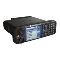
Figure 64: View of the Ethernet Control Head (eCH) with Mobile Microphone Port Connector
Number Description
1 View of the Ethernet Control Head’s Mobile Microphone Port Connector
2 Ethernet Control Head
68015000181-LB
Chapter 5: Connectors and PIN Assignment
106 Send Feedback

 Loading...


