4 Ground 18
Mobile Microphone Port (MMP)
1 1_WIRE 16
2 GPIO_3 / OTG-ID / RTSc (PTT) 4
3 Speaker to Headset 17
4 GPIO_2 / D- / RxDc 6
5 GND (Ground) N/A
6 Opt_5V / VBUS 5
7 Mic+ 19
8 GPIO_1 / D+ / TxDc 7
9 GPIO_4 / CTSc / Keyfail (HOOK) 20
10 GPIO_0 / Pwr On 8
Customised Wire Color
BROWN / BLACK GPIO_9 1
ORANGE / BLACK GPIO_6 2
YELLOW / BLACK GPIO_8 3
LIGHT BLUE GPIO_2 6
TURQUOISE GPIO_1 7
GREEN / BLACK TX 10
BLUE / BLACK RX 11
GRAY / BLACK MIC_2 12
BLUE Ground 13
PINK / BLACK GPIO_5 14
BLACK / WHITE GPI_7 15
USB A JACK Signal subD 25 Pos
BROWN / WHITE RTS 23
RED / WHITE CTS 24
ORANGE / WHITE Power On 25
RED / BLACK Headset 17
YELLOW / WHITE Ground N/A
5.8.4
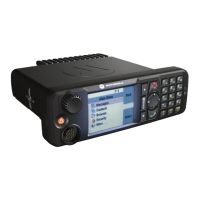
Connector and Pin Assignment for Cradle (Telephone Style Control
Head)
There are two connectors at the back of the TSCH Cradle:
• 10-PIN Audio Connector
• RJ50 Connector
68015000181-LB
Chapter 5: Connectors and PIN Assignment
Send Feedback 111
 Loading...