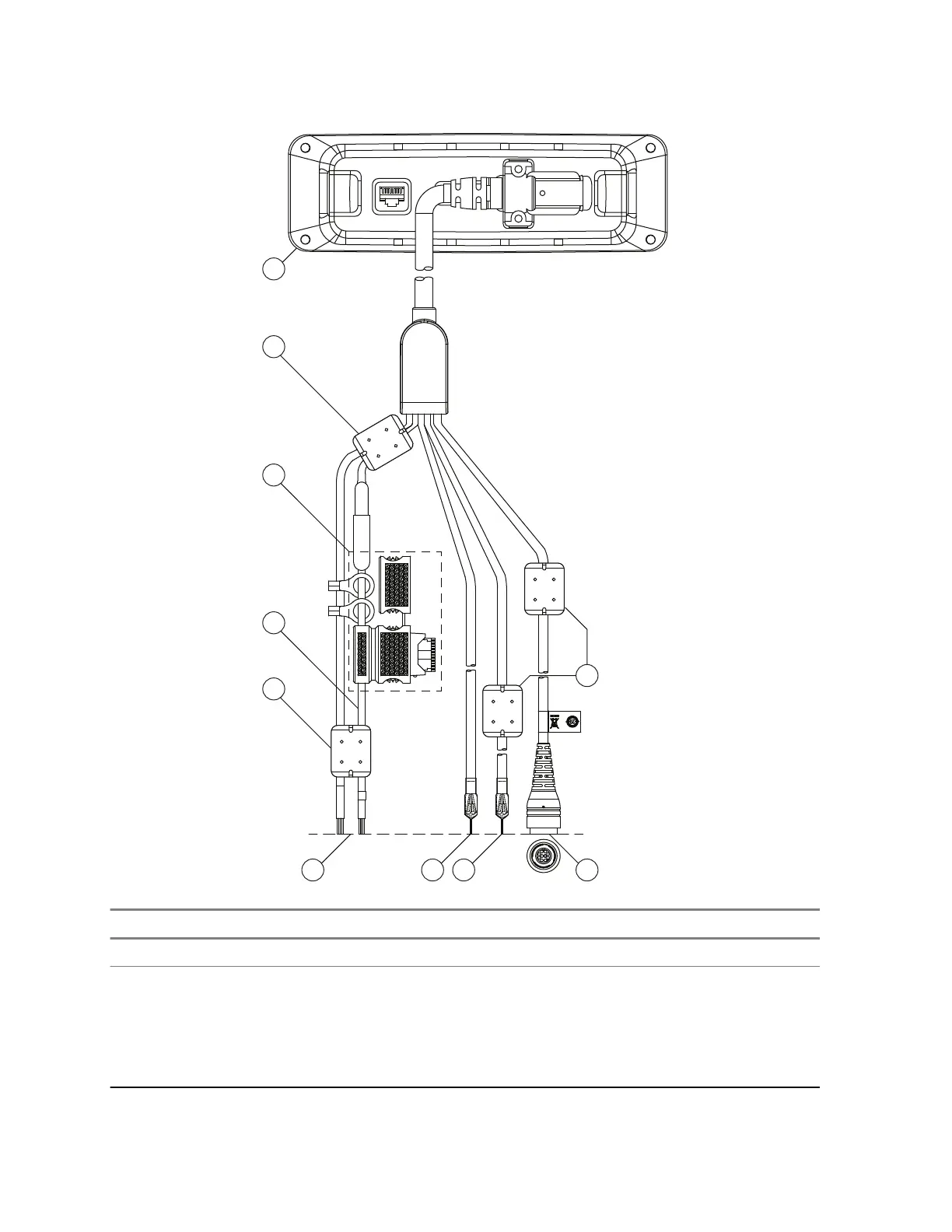
Figure 25: Accessories Expansion RECH Y-Cable
Number Item
1 Ethernet Remote Head with the cable connected (by the D-25 Connector)
2 Ground Wire and External Power Wire, Input supply 12 V/24 V: 2A – These connec-
tions correspond to P4 and P5 detailed in Figure 71: RECH Y-Cable Pin Diagram on
page 114 which provides the Pin Diagram of Cable PMKN4133. P4 is the 12/24V
positive DC supply input and P5 is Ground. This supply is for the Audio Power Amplifi-
er and is required to connect a Loudspeaker to the eCH. This is the only Power con-
nection that allows 12 V or 24 V operation, all other Power supplies must be 12 V.
Table continued…
68015000181-LB
Chapter 4: Radio Installation
64 Send Feedback
 Loading...