Chapter 5
Connectors and PIN Assignment
5.1
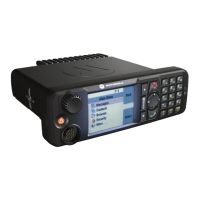
Transceiver Rear Side
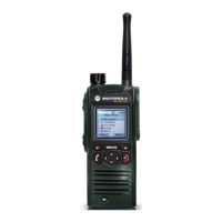
Figure 53: Location of Accessory Connector – Rear Side
CAUTION: The accessory connections shown are not compatible to some other models of
Motorola radios. Check the appropriate accessory or technical manual for further information.
Table 50: 26–PIN Accessory Connector
PIN Function Description
1 UART1_TXD / USBx_D+ USB 1.1 – Default Host
RS232 or UART2 – Alternative Setting
NOTICE: When Expansion Head is connected —
the connection is USB1.1. UART2 is configured
on DB9 interface on the expansion Head. The ra-
dio monitors DB9 interface to detect cable con-
nection/disconnection based on PIN voltage level
of RX and DTR lines.
2 UART1_RXD / USBx_D-
3 UART1_RTS / USBx_VBUS
4 GND_USBx
5 1-WIRE 1-Wire standard port (pulled via 2K2 to 5 V inside U600),
Data for RMN5054_ Microphone
6 KEYFAIL / FLASH Key load (pulled via 10 K to 5 V)
Flash input (>10 V will trigger Flash mode)
7 SWB + A+ voltage (limited to 14 V) with 1 A current limitation
8 GND_MAIN Main and power ground
9 SPEAKER- Loudspeaker (PA) out-
put –
WARNING:
Do not ground! See
Appendix for Rated
Audio Power.
Do not attach audio
accessories single-
ended between the
Speaker out (+ or -)
and ground on rear
Table continued…
68015000181-LB
Connectors and PIN Assignment
Send Feedback 93
 Loading...