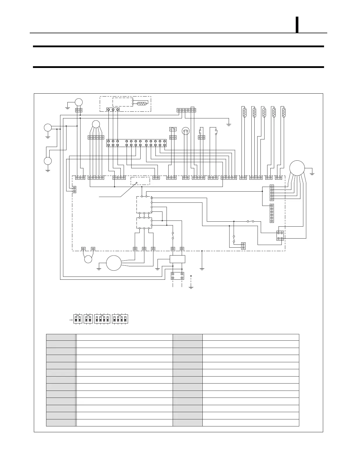
5. ELECTRICAL SYSTEM
ILL00283-01
12
G
G
CN
107
CN
106
CN
105
2
CN
104
CN
103
CN
101
CN
102
CN1
F3
F2
WMC
1
CN3
CN2CN4
#2~#4 : N/A
P C
AC 208/230 V
1-PHASE, 60 Hz
EXV
MDP
1 4 1
Y1
1
Y2
1
G
1
G1
1
E+
1111
E-
Millivolt
Thermostat
CTS1
L+
1 2 3 4
CN20
EWTS
CN19
L-
5
CTS3
C4 G4
DSW1 DSW2 DSW3
RTS2
DSW4
MF2
CN
HPRS
15
RB
Fire
Alarm
Input
TB2
Output
Signal
41
OLC
CN5
13
CN6 CN7 CN8
2
FLTS
SW
F1
2
425332
12
16
IND
MC
MF1
1
5
1
6
2
1
43
1
2
12
RT
1
2
TB1
CN9 CN10 CN11
NF
1 2
CN14 CN12CN13
CN18
STI
Module
CN17
G
1 2 3 4
DIP SWITCH
CTS2
OFF (DEFAULT)
DSW1
#1 ON : ENABLES MILLIVOLT WALL THERMOSTAT (MWT)
OFF : ENABLES WALL MOUNTED CONTROLLER (WMC)
#2 : N/A
RTS1
DSW2
#1 : ON : INITIALIZES FAN MOTOR
#2 : N/A
DSW3
#1 : ON : TEST MODE
DSW4 : N/A
CONTROL
CIRCUIT
Power
Supply
Circuit
1 2
GG
G
G
MF3
G
G
DIP SWITCH
2
1
2
1
TB1 Terminal Block 1
FLTS Float Switch
HPRS High-Pressure Switch
TB2 Terminal Block 2
WMC
RB Relay Board
F1 Fuse 1
MC Compressor Motor
OLC Compressor Overload Relay
F3 Fuse 3 For Evaporator Fan Motor MF2 AC Fan Motor
MF1 Evaporator Fan Motor
RTS1 WMC Room Thermistor
MF3 AC Fan Motor
MDP Internal Drain Pump Motor
RTS2 Evaporator Inlet Air Thermistor
EXV Electronic Expansion Valve
EWTS Entering Water Thermistor
NF Noise Filter
CTS1 Condenser Thermistor
IND Inductor Coil
CTS2 Evaporator Pipe Inlet Thermistor
SW Stop Switch
CTS3 Evaporator Pipe Outlet Thermistor
CN Connector For Optional Condensate Pump
G Ground
Wall Mounted Controller