Repair Section
74
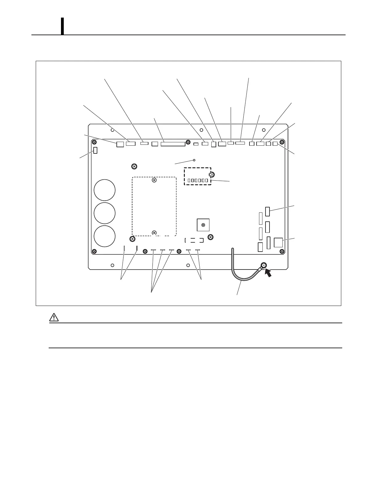
(1) Relay board
WARNING
• Do not touch the relay board until the green LED7 is turned off. Failure to follow this
warning may lead to electrical shock.
Removal of Relay Board
1) Disconnect the power at the source.
2) Loosen the bottom screw. (See page 68.)
3) Take out the nine (9) screws, and then remove the service panel. (See page 68.)
4) Disconnect all connectors from the relay board (15 connectors, 7 connections on the relay).
Refer to the figure “Relay board” to identify the relay connections and the connectors marked as
CN##. (To ensure easy reinstallation, be sure to label each connector wire as you remove them)
5) Take out the six (6) screws, and remove the relay board. The ground line for the relay board is
tightened together with the bottom right screw. (As shown in the illustration above, the relay
board and bracket assembly are replaced as a set.)
ILL00249-01
CN18
CN17
CN19
CN20
CN21
CN6
CN8
CN10
CN7
CN9
CN11
CN5
LED1
LED2
LED3
LED4
LED5
LED6
CN12
CN13
CN14
CN4
CN2CN3
CN1
CN106
CN107
to Output Signal
to Internal
Drain Pump Motor
and AC Fan Motor
to Electronic
Expansion Valve
to Wall Mounted
Controller
DIP Switch
to Condenser
Thermistor
to Entering
Water Thermistor
(EWTS)
to Noise Filter
Ground Connection
Ground Line
to Compressor
to Inductor Coil
to Evaporator
Fan Motor
LED 1~6
to Evaporator
Fan Motor
to High-Pressure
Switch
to Compressor
Overlord Relay
to Float
Switch
to Stop
Switch
to Millivolt
Thermostat
to Evaporator
Inlet Air
Thermistor
to Evaporator Pipe
Inlet Thermistor and
Evaporator Outlet
Thermistor
CN103
CN101
CN102
CN104
CN105
LED 7