ioLogik E1200 Series Using the Web Console
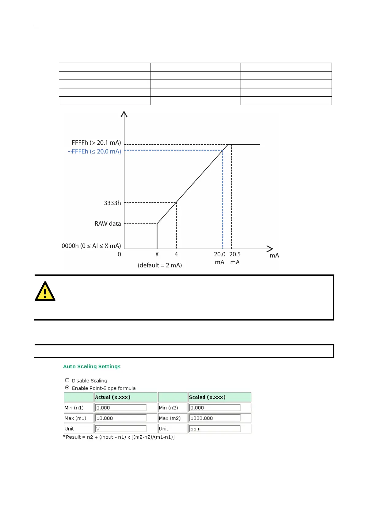
Users can define Burn Out (BO) values (default = 2 mA) for selected ranges. When input values are in the
Burn Out range, raw data will register as 0000h to indicate that the analog input has burned out. The definition
of raw data is as follows:
Burnout Value (BO) 0.0 < BO < 4.0 User defined (default 2 mA)
Burnout State 0 ≤ AI < BO mA S/W output 0000h
Under Range BO ≤ AI < 4 mA S/W output raw data
Normal Range 4 ≤AI ≤ 20.00 mA S/W output raw data until FFFEh
Over Range XX > 20.00 mA S/W output FFFFh
ATTENTION
When configuring the jumpers to select voltage or current measurement for the AI channels, open the cover by
first removing the screw on the back panel. For details on jumper settings, see the
Jumper Settings (DIO
section in Chapter 2.
Selecting Enable Point-Slope formula on the Auto Scaling Settings page will linearly convert the actual
current or voltage value into other user-defined units, such as percentage or ppm (parts per million).
Modbus address differs from the original value.