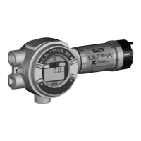
ULTIMA X
®
Series
GB
31
3.3 Installing the ULTIMA XA Gas Monitor
(1) Remove lid and drill enclosure for power, signal and optional relay cable entry.
Use one of the following methods to mount the general purpose ULTIMA XA Gas
Monitor/Less Sensor or the ULTIMA XA Gas Monitor:
(2) Use mounting holes in the corners of the ULTIMA XA enclosure to mount di-
rectly to a wall.
The ULTIMA XA gas sensor is not shipped attached to the main enclosure.
(3) Ensure the sensor wiring harness is through the entry and the sensor is point-
ed downward.
3.4 Electrical Connection for the ULTIMA® X Series Instruments
During the assembly, the ULTIMA XE Gas Monitor enclosure can be ro-
tated 360°, to ensure easy access to any of the four cable entries. For
correct positioning of the display, the electronics assembly can be in-
stalled in any of the four self-aligning positions.
Attention!
ULTIMA® X Series instruments must be installed only in compliance
with the applicable regulations, otherwise the safe operation of the in-
strument is not guaranteed.
During installation, use the internal earth connection to ground the in-
struments.
If an external earth connection is permitted or demanded by the local au-
thorities, it serves merely as additional earthing.

 Loading...


