Home
MSA
Measuring Instruments
Ultima X Series
MSA Ultima X Series User Manual
5
of 1
of 1 rating
162 pages
Give review
Manual
Specs
To Next Page
To Next Page
To Previous Page
To Previous Page
Loading...
MSA
Appendix: Electrical Installation
ULTIMA
X
®
Series
78
GB
9.13
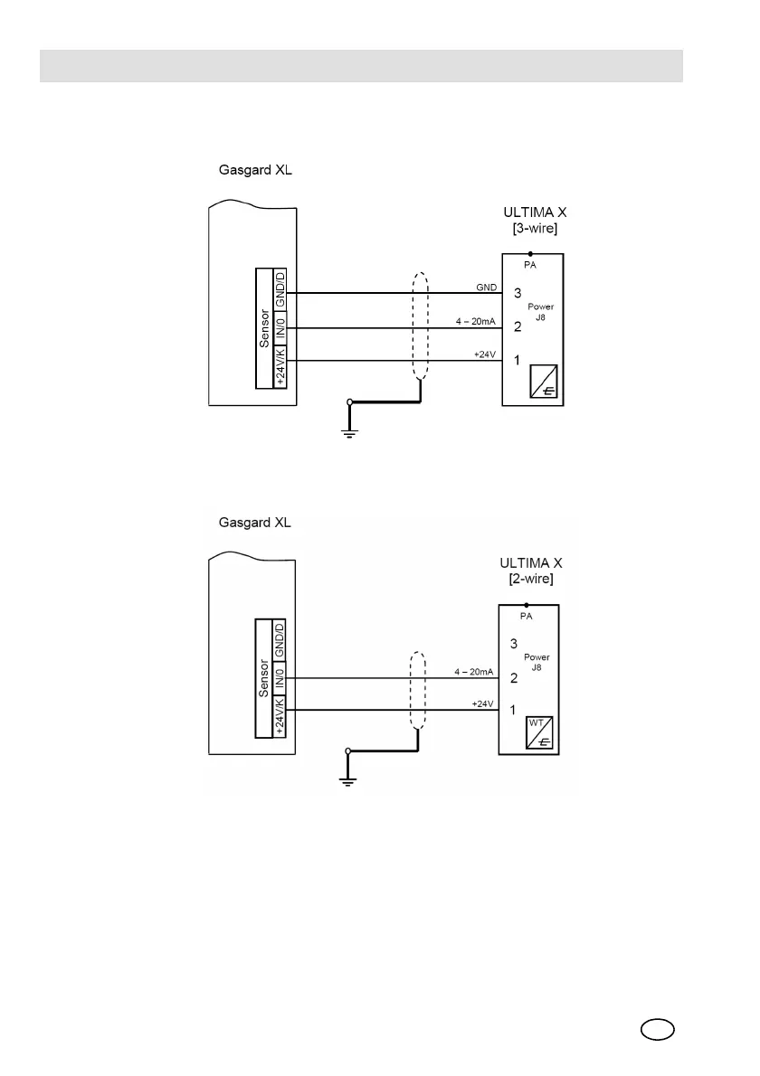
Connection Drawings -
Gasgard
Fig. 19
Connection drawing - ULTIMA X [3-wire] to Gasgard XL
Fig. 20
Connection drawing - ULTIMA X [2-wire] to Gasgard XL
1
Channel card - Gasgard XL
2
ULTIMA X
1
Channel card - Gasgard XL
2
ULTIMA X
77
79
Table of Contents
Default Chapter
3
Ec Declaration of Conformity
3
Table of Contents
11
1 Safety Regulations
15
Correct Use
15
Liability Information
15
Safety and Precautionary Measures to be Adopted
16
2 Description
19
Marking, Certificates and Approvals According to the Directive 94/9/EC [ ATEX ]
19
Overview
25
3 Installation
29
Instructions for Installation
29
Installation with ULTIMA® X Series Mounting Kit
30
Installing the ULTIMA XA Gas Monitor
31
Electrical Connection for the ULTIMA® X Series Instruments
31
ULTIMA® X Series Remote Sensor Module Installation
35
4 Operation
37
Hand-Held Controller and Calibrator
37
HART Compatible Communications Interface
38
Commissioning
38
5 Calibration
39
Calibration Basics
40
Initial Calibration
44
Regular Calibration
46
6 Maintenance
51
ULTIMA XIR Cleaning Procedure
51
Replacing the ULTIMA XE/XA Sensor
53
7 Technical Data
55
Dimensions, Weight
55
Performance Specifications
56
Measuring Accuracy
58
ULTIMA XE - ATEX Performance Approval
59
ULTIMA XIR - ATEX Performance Approval
61
8 Ordering Information
64
Gas Monitors, Accessories
64
Replacement Parts
66
9 Appendix: Electrical Installation
67
Installation Outline Drawing [CE] - ULTIMA XE
67
Installation Outline Drawing [CE] - ULTIMA XE with XIR Sensor
68
Installation Outline Drawing [CE] - ULTIMA XA
69
Installation - Mounting Bracket
70
Remote Non-Reactive Sensor and Mounting Bracket
71
HART Module
72
ULTIMA XIR Remote Sensor
73
Installation Outline Drawing [CE] - ULTIMA XE Wiring Connections
74
HART Module Connections
75
Connection to MSA Controllers
75
Connection Drawings - SUPREMA
76
Connection Drawings - 9010/9020
77
Connection Drawings - Gasgard
78
Cable Lengths and Cross-Section - Gas Monitors
79
Cable Lengths and Cross-Section - Remote Sensor Module *)
80
10 Appendix: Instrument Specifications
80
Instrument Operation
80
Sensor Response to Interferants
82
11 Appendix: Instrument Messages
88
Messages During Instrument Operation
88
Messages During Instrument Configuration
88
Instructions for Troubleshooting
89
12 Appendix: Optional Internal Relays and RESET Button
92
General
92
Mounting and Wiring of Instruments
92
Alarm Relays
94
Fault Relay [Trouble]
95
Optional RESET Button
95
Calibration with RESET Button
96
Relay Connections
96
13 Appendix: HART Specific Information
98
HART Field Device Specification
98
Universal Commands
103
Common-Practice Commands
103
Gas Type Descriptions
128
Alarm Control Actions
128
Calibration Modes
128
Sensor Status Codes
129
Gas Table Values
130
Performance
131
Capability Checklist
133
Default Configuration
134
Calibration Using a HART® Communicator
134
Standard Calibration Procedures
136
Initial Calibration Procedures
140
User [Stepped] Calibration Procedures
140
Sample Calibration Display Screens
143
Troubleshooting
156
Other manuals for MSA Ultima X Series
Instruction Manual
61 pages
Installation & Maintenance Instructions
142 pages
Quick Start Guide
18 pages
Safety Manual
16 pages
5
Based on 1 rating
Ask a question
Give review
Questions and Answers:
Need help?
Do you have a question about the MSA Ultima X Series and is the answer not in the manual?
Ask a question
MSA Ultima X Series Specifications
General
Brand
MSA
Model
Ultima X Series
Category
Measuring Instruments
Language
English
Related product manuals
MSA altair 4
59 pages
MSA Chemgard
74 pages
MSA Chillgard RT
124 pages
MSA PrimaX I
80 pages
MSA PrimaX P
80 pages
MSA Chillgard LS
48 pages

 Loading...


