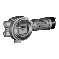
Appendix: Optional Internal Relays and RESET ButtonMSA
ULTIMA X
®
Series
GB
97
To connect the relay, the ULTIMA® X Series Gas Monitor must be opened. Pro-
ceed as described below:
(1) Remove theULTIMA X
®
Series Gas Monitor enclosure cover.
(2) Pull the terminal plugs to release them from the now accessible printed board.
(3) Feed the cable [not included] into the enclosure and connect it to the appropri-
ate terminal plugs.
(4) Make sure that each cable conductor is connected correctly to ensure proper
functioning of the Gas Monitor.
(5) If installing a RESET push-button:
Feed a 2-wire cable to the J10 terminal plug [Figure 4].
Connect the 2-wire cable to the two connections of the J10 terminal plug.
Identify the cable to allow proper connection at the push-button.
Route the cable to the push-button switch and connect the cable to it.
(6) Re-install the connector plugs to the correct printed circuit board locations.
Make sure the connector terminal plugs are completely pushed in to the print-
ed circuit board sockets.
(7) Pull the cable from the instrument to remove any excess slack.
(8) Replace the ULTIMA® X Series Gas Monitor cover.
Attention!
Before connecting the cable to ULTIMA® X Series Gas Monitors, dis-
connect or isolate the monitor power source otherwise there is danger of
electric shock.
To enable correct connection of all plugs note their location before re-
moving them.
Route the 2-wire cable to avoid electrical interference from relay wiring.
To avoid unwanted electrical noise it is important not to have any excess
wire or cable inside the enclosure.

 Loading...


